
An electrical insulator is a material in which electric current does not flow freely. The atoms of the insulator have tightly bound electrons which cannot readily move. Other materials—semiconductors and conductors—conduct electric current more easily. The property that distinguishes an insulator is its resistivity; insulators have higher resistivity than semiconductors or conductors. The most common examples are non-metals.

A high-voltage direct current (HVDC) electric power transmission system uses direct current (DC) for electric power transmission, in contrast with the more common alternating current (AC) transmission systems.

Components of an electrical circuit are electrically connected if an electric current can run between them through an electrical conductor. An electrical connector is an electromechanical device used to create an electrical connection between parts of an electrical circuit, or between different electrical circuits, thereby joining them into a larger circuit. Most electrical connectors have a gender – i.e. the male component, called a plug, connects to the female component, or socket. The connection may be removable, require a tool for assembly and removal, or serve as a permanent electrical joint between two points. An adapter can be used to join dissimilar connectors.
In electrical engineering, partial discharge (PD) is a localized dielectric breakdown (DB) of a small portion of a solid or fluid electrical insulation (EI) system under high voltage (HV) stress. While a corona discharge (CD) is usually revealed by a relatively steady glow or brush discharge (BD) in air, partial discharges within solid insulation system are not visible.
Electrical wiring in North America follows the regulations and standards applicable at the installation location. It is also designed to provide proper function, and is also influenced by history and traditions of the location installation.

Electrical wiring is an electrical installation of cabling and associated devices such as switches, distribution boards, sockets, and light fittings in a structure.

An overhead power line is a structure used in electric power transmission and distribution to transmit electrical energy along large distances. It consists of one or more conductors suspended by towers or poles. Since most of the insulation is provided by air, overhead power lines are generally the lowest-cost method of power transmission for large quantities of electric energy.

A power cable is an electrical cable, an assembly of one or more electrical conductors, usually held together with an overall sheath. The assembly is used for transmission of electrical power. Power cables may be installed as permanent wiring within buildings, buried in the ground, run overhead, or exposed. Power cables that are bundled inside thermoplastic sheathing and that are intended to be run inside a building are known as NM-B.
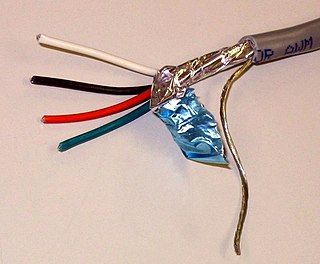
A shielded cable or screened cable is an electrical cable that has a common conductive layer around its conductors for electromagnetic shielding. This shield is usually covered by an outermost layer of the cable. Common types of cable shielding can most broadly be categorized as foil type, contraspiralling wire strands or both. A longitudinal wire may be necessary with dielectric spiral foils to short out each turn.
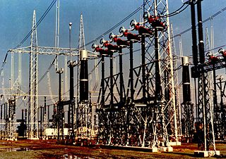
In an electric power system, a switchgear is composed of electrical disconnect switches, fuses or circuit breakers used to control, protect and isolate electrical equipment. Switchgear is used both to de-energize equipment to allow work to be done and to clear faults downstream. This type of equipment is directly linked to the reliability of the electricity supply.
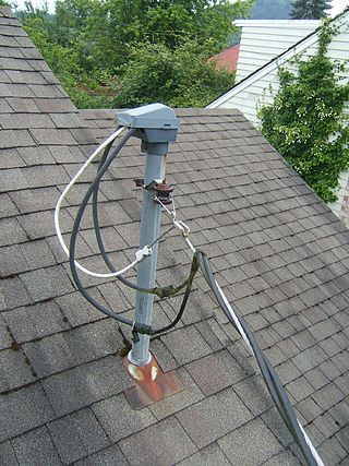
A weatherhead, also called a weathercap, service head, service entrance cap, or gooseneck (slang) is a weatherproof service drop entry point where overhead power or telephone wires enter a building, or where wires transition between overhead and underground cables. At a building the wires enter a conduit, a protective metal pipe, and the weatherhead is a waterproof cap on the end of the conduit that allows the wires to enter without letting in water. It is shaped like a hood, with the surface where the wires enter facing down at an angle of at least 45°, to shield it from precipitation. A rubberized gasket makes for a tight seal against the wires. Before they enter the weatherhead, a drip loop is left in the overhead wires, which permits rain water that collects on the wires to drip off before reaching the weatherhead.

In electric power, a bushing is a hollow electrical insulator that allows an electrical conductor to pass safely through a conducting barrier such as the case of a transformer or circuit breaker without making electrical contact with it. Bushings are typically made from porcelain, though other insulating materials are also used.

In electrical engineering, treeing is an electrical pre-breakdown phenomenon in solid insulation. It is a damaging process due to partial discharges and progresses through the stressed dielectric insulation, in a path resembling the branches of a tree. Treeing of solid high-voltage cable insulation is a common breakdown mechanism and source of electrical faults in underground power cables.

Knob-and-tube wiring is an early standardized method of electrical wiring in buildings, in common use in North America from about 1880 to the 1930s. It consisted of single-insulated copper conductors run within wall or ceiling cavities, passing through joist and stud drill-holes via protective porcelain insulating tubes, and supported along their length on nailed-down porcelain knob insulators. Where conductors entered a wiring device such as a lamp or switch, or were pulled into a wall, they were protected by flexible cloth insulating sleeving called loom. The first insulation was asphalt-saturated cotton cloth, then rubber became common. Wire splices in such installations were twisted together for good mechanical strength, then soldered and wrapped with rubber insulating tape and friction tape, or made inside metal junction boxes.
In an electric power system, a fault or fault current is any abnormal electric current. For example, a short circuit is a fault in which a live wire touches a neutral or ground wire. An open-circuit fault occurs if a circuit is interrupted by a failure of a current-carrying wire or a blown fuse or circuit breaker. In three-phase systems, a fault may involve one or more phases and ground, or may occur only between phases. In a "ground fault" or "earth fault", current flows into the earth. The prospective short-circuit current of a predictable fault can be calculated for most situations. In power systems, protective devices can detect fault conditions and operate circuit breakers and other devices to limit the loss of service due to a failure.

In civil engineering, undergrounding is the replacement of overhead cables providing electrical power or telecommunications, with underground cables. It helps in wildfire prevention and in making the power lines less susceptible to outages during high winds, thunderstorms or heavy snow or ice storms. An added benefit of undergrounding is the aesthetic quality of the landscape without the powerlines. Undergrounding can increase the capital cost of electric power transmission and distribution but may decrease operating costs over the lifetime of the cables.

An aerial cable or air cable is an insulated cable usually containing all conductors required for an electrical distribution system or a telecommunication line, which is suspended between utility poles or electricity pylons. As aerial cables are completely insulated there is no danger of electric shock when touching them and there is no requirement for mounting them with insulators on pylons and poles. A further advantage is they require less right of way than overhead lines for the same reason. They can be designed as shielded cables for telecommunication purposes. If the cable falls, it may still operate if its insulation is not damaged.

A high-voltage cable is a cable used for electric power transmission at high voltage. A cable includes a conductor and insulation. Cables are considered to be fully insulated. This means that they have a fully rated insulation system that will consist of insulation, semi-con layers, and a metallic shield. This is in contrast to an overhead line, which may include insulation but not fully rated for operating voltage. High-voltage cables of differing types have a variety of applications in instruments, ignition systems, and alternating current (AC) and direct current (DC) power transmission. In all applications, the insulation of the cable must not deteriorate due to the high-voltage stress, ozone produced by electric discharges in air, or tracking. The cable system must prevent contact of the high-voltage conductor with other objects or persons, and must contain and control leakage current. Cable joints and terminals must be designed to control the high-voltage stress to prevent the breakdown of the insulation.
CEAR namely Central Electricity Authority Regulations, 2010 are regulations framed by Central Electricity Authority of India under Indian Electricity Act, 2003, to regulate measures relating to safety and electric supply in India.
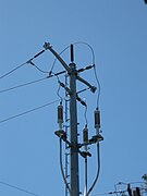 Transition of a 60kv powerline between overhead and underground
 Transition of a 4160 Volt powerline from overhead to underground
 Pothead for one phase


