Printed circuit board milling

Last updated
A milled printed circuit board Milled PCB.JPG
A milled printed circuit board

Printed circuit board milling (also: isolation milling) is the milling process used for removing areas of copper from a sheet of printed circuit board (PCB) material to recreate the pads, signal traces and structures according to patterns from a digital circuit board plan known as a layout file. [1] Similar to the more common and well known chemical PCB etch process, the PCB milling process is subtractive: material is removed to create the electrical isolation and ground planes required. However, unlike the chemical etch process, PCB milling is typically a non-chemical process and as such it can be completed in a typical office or lab environment without exposure to hazardous chemicals. High quality circuit boards can be produced using either process. [2] In the case of PCB milling, the quality of a circuit board is chiefly determined by the system's true, or weighted, milling accuracy and control as well as the condition (sharpness, temper) of the milling bits and their respective feed/rotational speeds. By contrast, in the chemical etch process, the quality of a circuit board depends on the accuracy and/or quality of the mask used to protect the copper from the chemicals and the state of the etching chemicals. [3]

Contents

Advantages

PCB milling has advantages for both prototyping and some special PCB designs. The biggest benefit is that one does not have to use chemicals to produce PCBs.

When creating a prototype, outsourcing a board takes time. An alternative is to make a PCB in-house. Using the wet process, in-house production presents problems with chemicals and disposing thereof. High-resolution boards using the wet process are hard to achieve and still, when done, one still has to drill and eventually cut out the PCB from the base material.

CNC machine prototyping can provide a fast-turnaround board production process without the need for wet processing. [4] If a CNC machine is already used for drilling, this single machine could carry out both parts of the process, drilling and milling. A CNC machine is used to process drilling, milling and cutting. [5]

Many boards that are simple for milling would be very difficult to process by wet etching and manual drilling afterward in a laboratory environment without using top-of-the-line systems that usually cost many times more than CNC milling machines. [6]

In mass production, milling is unlikely to replace etching although the use of CNC is already standard practice for drilling the boards.

Hardware

A PCB milling system is a single machine that can perform all of the required actions to create a prototype board, with the exception of inserting vias and through hole plating . Most of these machines require only a standard AC mains outlet and a shop-type vacuum cleaner for operation.

Software

Software for milling PCBs is usually delivered by the CNC machine manufacturer. Most of the packages can be split in two main categories – raster and vector. [7]

Software that produces tool paths using raster calculation method tends to have lower resolution of processing than the vector based software since it relies on the raster information it receives. [8] [9]

Mechanical system

The mechanics behind a PCB milling machine are fairly straightforward and have their roots in CNC milling technology. A PCB milling system is similar to a miniature and highly accurate NC milling table. For machine control, positioning information and machine control commands are sent from the controlling software via a serial port or parallel port connection to the milling machine's on-board controller. The controller is then responsible for driving and monitoring the various positioning components which move the milling head and gantry and control the spindle speed. Spindle speeds can range from 30,000 RPM to 100,000 RPM depending on the milling system, with higher spindle speeds equating to better accuracy, in a nutshell the smaller the tool diameter the higher RPM you need. [10] Typically this drive system comprises non-monitored stepper motors for the X/Y axis, an on-off non-monitored solenoid, pneumatic piston or lead screw for the Z-axis, and a DC motor control circuit for spindle speed, none of which provide positional feedback. More advanced systems provide a monitored stepper motor Z-axis drive for greater control during milling and drilling as well as more advanced RF spindle motor control circuits that provide better control over a wider range of speeds.

X and Y-axis control

For the X and Y-axis drive systems most PCB milling machines use stepper motors that drive a precision lead screw. The lead screw is in turn linked to the gantry or milling head by a special precision machined connection assembly. To maintain correct alignment during milling, the gantry or milling head's direction of travel is guided along using linear or dovetailed bearing(s). Most X/Y drive systems provide user control, via software, of the milling speed, which determines how fast the stepper motors drive their respective axes.

Z-axis control

Z-axis drive and control are handled in several ways. The first and most common is a simple solenoid that pushes against a spring. When the solenoid is energized it pushes the milling head down against a spring stop that limits the downward travel. The rate of descent as well as the amount of force exerted on the spring stop must be manually set by mechanically adjusting the position of the solenoid's plunger.

The second type of Z-axis control is through the use of a pneumatic cylinder and a software-driven gate valve. Due to the small cylinder size and the amount of air pressure used to drive it there is little range of control between the up and down stops. Both the solenoid and pneumatic system cannot position the head anywhere other than the endpoints, and are therefore useful for only simple 'up/down' milling tasks. The final type of Z-axis control uses a stepper motor that allows the milling head to be moved in small accurate steps up or down. Further, the speed of these steps can be adjusted to allow tool bits to be eased into the board material rather than hammered into it. The depth (number of steps required) as well as the downward/upward speed is under user control via the controlling software.

One of the major challenges with milling PCBs is handling variations in flatness. Since conventional etching techniques rely on optical masks that sit right on the copper layer they can conform to any slight bends in the material so all features are replicated faithfully.

When milling PCBs however, any minute height variations encountered when milling will cause conical bits to either sink deeper (creating a wider cut) or rise off the surface, leaving an uncut section. Before cutting some systems perform height mapping probes across the board to measure height variations and adjust the Z values in the G-code beforehand.

Tooling

PCBs may be machined with conventional endmills, conical d-bit cutters, and spade mills. D-bits and spade mills are cheap and as they have a small point allow the traces to be close together. Taylor's equation, Vc Tn = C, can predict tool life for a given surface speed. [11]

Alternatives

A method with similar advantages to mechanical milling is laser etching and laser drilling. Etching PCBs with lasers offers the same advantages as mechanical milling in regards to quick turnaround times, but the nature of the laser etching process is preferable to both milling and chemical etching when it comes to physical variations exerted on the object. Whereas mechanical milling and chemical etching exact physical stress on the board, laser etching offers non-contact surface removal, making it a superior option for PCBs where precision and geometric accuracy are at a premium, such as RF and microwave designs. [12] Laser drilling is more precise, has extremely low power consumption compared with other techniques, requires less maintenance, does not use lubricants or drill bits, low rates of wear, does not use abrasive materials, does not ruin the boards, is more eco friendly, and in the most high-powered machines, the drilling is instant, but is expensive. An additional emerging alternative to milling and laser etching is an additive approach based upon printing the conductive trace. Such PCB printers come at a range of price points and with differing features but also offer rapid in-house circuit manufacture, with very little to no waste. An example of such a technology that produces simpler, low layer count PCBs is Voltera. [13] A system at the higher layer-count end of the additive manufacturing approach is Nano Dimension's DragonFly technology [14] which prints complex high layer count circuits as well as electro-mechanical parts.

Related Research Articles

<span class="mw-page-title-main">Router (woodworking)</span> Woodworking power tool

The router is a power tool with a flat base and a rotating blade extending past the base. The spindle may be driven by an electric motor or by a pneumatic motor. It routs an area in hard material, such as wood or plastic. Routers are used most often in woodworking, especially cabinetry. They may be handheld or affixed to router tables. Some woodworkers consider the router one of the most versatile power tools.

<span class="mw-page-title-main">Printed circuit board</span> Board to support and connect electronic components

A printed circuit board (PCB), also called printed wiring board (PWB), is a medium used to connect or "wire" components to one another in a circuit. It takes the form of a laminated sandwich structure of conductive and insulating layers: each of the conductive layers is designed with a pattern of traces, planes and other features etched from one or more sheet layers of copper laminated onto and/or between sheet layers of a non-conductive substrate. Electrical components may be fixed to conductive pads on the outer layers in the shape designed to accept the component's terminals, generally by means of soldering, to both electrically connect and mechanically fasten them to it. Another manufacturing process adds vias, plated-through holes that allow interconnections between layers.

<span class="mw-page-title-main">Computer-aided manufacturing</span> Use of software to control industrial processes

Computer-aided manufacturing (CAM) also known as computer-aided modeling or computer-aided machining is the use of software to control machine tools in the manufacturing of work pieces. This is not the only definition for CAM, but it is the most common. It may also refer to the use of a computer to assist in all operations of a manufacturing plant, including planning, management, transportation and storage. Its primary purpose is to create a faster production process and components and tooling with more precise dimensions and material consistency, which in some cases, uses only the required amount of raw material, while simultaneously reducing energy consumption. CAM is now a system used in schools and lower educational purposes. CAM is a subsequent computer-aided process after computer-aided design (CAD) and sometimes computer-aided engineering (CAE), as the model generated in CAD and verified in CAE can be input into CAM software, which then controls the machine tool. CAM is used in many schools alongside CAD to create objects.

<span class="mw-page-title-main">Metalworking</span> Process of making items from metal

Metalworking is the process of shaping and reshaping metals to create useful objects, parts, assemblies, and large scale structures. As a term it covers a wide and diverse range of processes, skills, and tools for producing objects on every scale: from huge ships, buildings, and bridges down to precise engine parts and delicate jewelry.

<span class="mw-page-title-main">Stripboard</span>

Stripboard is the generic name for a widely used type of electronics prototyping material for circuit boards characterized by a pre-formed 0.1 inches (2.54 mm) regular (rectangular) grid of holes, with wide parallel strips of copper cladding running in one direction all the way across one side of on an insulating bonded paper board. It is commonly also known by the name of the original product Veroboard, which is a trademark, in the UK, of British company Vero Technologies Ltd and Canadian company Pixel Print Ltd. It was originated and developed in the early 1960s by the Electronics Department of Vero Precision Engineering Ltd (VPE). It was introduced as a general-purpose material for use in constructing electronic circuits - differing from purpose-designed printed circuit boards (PCBs) in that a variety of electronics circuits may be constructed using a standard wiring board.
<span class="mw-page-title-main">Numerical control</span> Computer control of machine tools

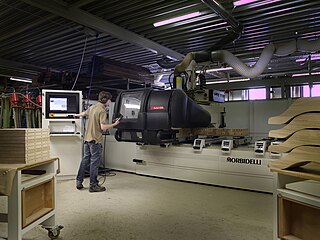
In machining, numerical control, also called computer numerical control (CNC), is the automated control of tools by means of a computer. It is used to operate tools such as drills, lathes, mills, grinders, routers and 3D printers. CNC transforms a piece of material into a specified shape by following coded programmed instructions and without a manual operator directly controlling the machining operation.

<span class="mw-page-title-main">Drilling</span> Cutting process that uses a drill bit to cut a circular hole into the workpiece

Drilling is a cutting process where a drill bit is spun to cut a hole of circular cross-section in solid materials. The drill bit is usually a rotary cutting tool, often multi-point. The bit is pressed against the work-piece and rotated at rates from hundreds to thousands of revolutions per minute. This forces the cutting edge against the work-piece, cutting off chips (swarf) from the hole as it is drilled.

<span class="mw-page-title-main">CNC wood router</span>

A CNC wood router is a CNC router tool that creates objects from wood. CNC stands for computer numerical control. The CNC works on the Cartesian coordinate system for 3D motion control. Parts of a project can be designed in the computer with a CAD/CAM program, and then cut automatically using a router or other cutters to produce a finished part. The CNC router is ideal for hobbies, engineering prototyping, product development, art, and production work.

<span class="mw-page-title-main">Depaneling</span>

Depaneling is a process step in high-volume electronics assembly production. In order to increase the throughput of printed circuit board (PCB) manufacturing and surface mount (SMT) lines, PCBs are often designed so that they consist of many smaller individual PCBs that will be used in the final product. This PCB cluster is called a panel or multiblock. The large panel is broken up or "depaneled" as a certain step in the process - depending on the product, it may happen right after SMT process, after in-circuit test (ICT), after soldering of through-hole elements, or even right before the final assembly of the PCBA into the enclosure.

<span class="mw-page-title-main">Tool and cutter grinder</span>

A Tool and Cutter Grinder is used to sharpen milling cutters and tool bits along with a host of other cutting tools.

<span class="mw-page-title-main">Metal lathe</span> Machine tool used to remove material from a rotating workpiece

In machining, a metal lathe or metalworking lathe is a large class of lathes designed for precisely machining relatively hard materials. They were originally designed to machine metals; however, with the advent of plastics and other materials, and with their inherent versatility, they are used in a wide range of applications, and a broad range of materials. In machining jargon, where the larger context is already understood, they are usually simply called lathes, or else referred to by more-specific subtype names. These rigid machine tools remove material from a rotating workpiece via the movements of various cutting tools, such as tool bits and drill bits.

A via is an electrical connection between two or more metal layers, and are commonly used in printed circuit boards (PCB). Essentially a via is a small drilled hole that goes through two or more adjacent layers; the hole is plated with metal that forms an electrical connection through the insulating layers.

ColorCAM was both a CAD and a computer-aided manufacturing (CAM) system for printed circuit boards (PCB). Introduced in 1983 by Lothar Klein, LKSoft, it was one of the first systems running on a personal computer instead of a workstation or mainframe, which was typically the case for all CAD applications at that time.

Digital modeling and fabrication is a design and production process that combines 3D modeling or computing-aided design (CAD) with additive and subtractive manufacturing. Additive manufacturing is also known as 3D printing, while subtractive manufacturing may also be referred to as machining, and many other technologies can be exploited to physically produce the designed objects.
<span class="mw-page-title-main">Spindle (tool)</span> Rotary unit of a machine tool

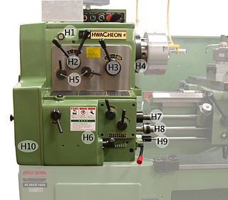
In machine tools, a spindle is a rotating axis of the machine, which often has a shaft at its heart. The shaft itself is called a spindle, but also, in shop-floor practice, the word often is used metonymically to refer to the entire rotary unit, including not only the shaft itself, but its bearings and anything attached to it. Spindles are electrically or pneumatically powered and come in various sizes. They are versatile in terms of material it can work with. Materials that spindles work with include embroidery, foam, glass, wood, etc.

<span class="mw-page-title-main">CNC router</span> Computer-controlled cutting machine

A computer numerical control (CNC) router is a computer-controlled cutting machine which typically mounts a hand-held router as a spindle which is used for cutting various materials, such as wood, composites, metals, plastics, glass, and foams. CNC routers can perform the tasks of many carpentry shop machines such as the panel saw, the spindle moulder, and the boring machine. They can also cut joinery such as mortises and tenons.
<span class="mw-page-title-main">Multiaxis machining</span> Manufacturing processes using tools that can move in 4 or more directions

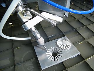
Multiaxis machining is a manufacturing process that involves tools that move in 4 or more directions and are used to manufacture parts out of metal or other materials by milling away excess material, by water jet cutting or by laser cutting. This type of machining was originally performed mechanically on large complex machines. These machines operated on 4, 5, 6, and even 12 axes which were controlled individually via levers that rested on cam plates. The cam plates offered the ability to control the tooling device, the table in which the part is secured, as well as rotating the tooling or part within the machine. Due to the machines size and complexity it took extensive amounts of time to set them up for production. Once computer numerically controlled machining was introduced it provided a faster, more efficient method for machining complex parts.

<span class="mw-page-title-main">WorkNC</span>

WorkNC is a Computer aided manufacturing (CAM) software developed by Sescoi for multi-axis machining.

<span class="mw-page-title-main">Milling (machining)</span> Removal of material from a workpiece using rotating tools

Milling is the process of machining using rotary cutters to remove material by advancing a cutter into a workpiece. This may be done by varying directions on one or several axes, cutter head speed, and pressure. Milling covers a wide variety of different operations and machines, on scales from small individual parts to large, heavy-duty gang milling operations. It is one of the most commonly used processes for machining custom parts to precise tolerances.

References

  1. Khandpur, R. S. (2005). Printed Circuit Boards: Design, Fabrication, Assembly and Testing. Tata McGraw-Hill Education. ISBN   9780070588141.
  2. Baschirotto, A.; Dallago, E.; Malcovati, P.; Marchesi, M.; Venchi, G. (2007-02-01). "A Fluxgate Magnetic Sensor: From PCB to Micro-Integrated Technology". IEEE Transactions on Instrumentation and Measurement. 56 (1): 25–31. doi:10.1109/TIM.2006.887218. ISSN   0018-9456. S2CID   27250870.
  3. Datta, M.; Osaka, Tetsuya; Schultze, J. Walter (2004-12-20). Microelectronic Packaging. CRC Press. p. 185. ISBN   9780203473689.
  4. Production Engineering. Penton/IPC., Incorporated. 1987.
  5. "PCB Rapid Prototype | WellPCB". www.wellpcb.com. Retrieved 2017-05-27.
  6. Richard Sewell. "Milled PCB for a ball-bearing sequencer control surface (The xylobearningococonutofivefivefiveophone)". Jarkman Enterprises.
  7. Piatt, Michael J.; Brown, Mark E.; Walters, Michael A. (1991). "Method for fabricating printed circuit boards".{{cite journal}}: Cite journal requires |journal= (help)
  8. Doudkin, Alexander; Inyutin, Alexander (2014-08-01). "The Defect and Project Rules Inspection on PCB Layout Image". International Journal of Computing. 5 (3): 107–111. doi: 10.47839/ijc.5.3.414 . ISSN   2312-5381.
  9. Vona, M. A.; Rus, D. (April 2005). "Voronoi Toolpaths for PCB Mechanical Etch: Simple and Intuitive Algorithms with the 3D GPU". Proceedings of the 2005 IEEE International Conference on Robotics and Automation. pp. 2759–2766. doi:10.1109/robot.2005.1570531. ISBN   978-0-7803-8914-4. S2CID   16599567.
  10. "Milling Machine Specifications". LPKF Laser & Electronics.
  11. Yoon, Hae-Sung; Moon, Jong-Seol; Pham, Minh-Quan; Lee, Gyu-Bong; Ahn, Sung-Hoon (2013). "Control of machining parameters for energy and cost savings in micro-scale drilling of PCBs". Journal of Cleaner Production. 54: 41–48. doi:10.1016/j.jclepro.2013.04.028.
  12. "LPKF Redirect". www.lpkfusa.com. Retrieved 2017-05-27.
  13. "Voltera".
  14. "NanoDImension".