Reconfigurable manufacturing system

Last updated

A reconfigurable manufacturing system (RMS) is one designed at the outset for rapid change in its structure, as well as its hardware and software components, in order to quickly adjust its production capacity and functionality within a part family in response to sudden market changes or intrinsic system change. [1] [2]

Contents

From 1996 to 2007 Yoram Koren received an NSF grant of $32.5 million [3] to develop the RMS science-base and its software and hardware tools, which were implemented in the automotive, aerospace, and engine factories.

A schematic diagram of Koren's RMS; drawn by Rod Hill RMS schematic.gif
A schematic diagram of Koren's RMS; drawn by Rod Hill

The term reconfigurability in manufacturing was likely coined by Kusiak and Lee. [4]

The RMS, as well as one of its components—the reconfigurable machine tool (RMT)—were invented in 1998 in the Engineering Research Center for Reconfigurable Manufacturing Systems (ERC/RMS) at the University of Michigan College of Engineering. [5] [6] [7] The RMS goal is summarized by the statement: "Exactly the capacity and functionality needed, exactly when needed".

Ideal reconfigurable manufacturing systems possess six core RMS characteristics: modularity, integrability, customized flexibility, scalability, convertibility, and diagnosability. [7] [8] A typical RMS will have several of these characteristics, though not necessarily all. When possessing these characteristics, RMS increases the speed of responsiveness of manufacturing systems to unpredicted events, such as sudden market demand changes or unexpected machine failures.. The RMS facilitates a quick production launch of new products, and allows for adjustment of production quantities that might unexpectedly vary. The ideal reconfigurable system provides exactly the functionality and production capacity needed, and can be economically adjusted exactly when needed. [9] These systems are designed and operated according to Yoram Koren's RMS principles.

The components of RMS are CNC machines, [10] reconfigurable machine tools, [6] [8] reconfigurable inspection machines [11] and material transport systems (such as gantries and conveyors) that connect the machines to form the system. Different arrangements and configurations of these machines will affect the system's productivity. [12] A collection of mathematical tools, which are defined as the RMS science base, may be utilized to maximize system productivity with the smallest possible number of machines.

Rationale for RMS

Globalization has created a new landscape for industry, one of fierce competition, short windows of market opportunity, and frequent changes in product demand. This change presents both a threat and an opportunity. To capitalize on the opportunity, industry needs to possess manufacturing systems that can produce a wide range of products within a product family. That range must meet the requirements of multiple countries and various cultures, not just one regional market. A design for the right mix of products must be coupled with the technical capabilities that allow for quick changeover of product mix and quantities that might vary dramatically, even on a monthly basis. Reconfigurable manufacturing systems have these capabilities.

RMS System Architecture and Operation

The system architecture of a typical RMS is shown below.

Reconfigurable Manufacturing System Architecture by Y. Koren RMS Architecture.png
Reconfigurable Manufacturing System Architecture by Y. Koren

The system is composed of stages: 10, 20, 30, 40, etc. Each stage consists of identical machines, such as CNC milling machines, or RMT machines. The system produces one product, for example, an automotive engine block or a cylinder head. The manufactured product moves on the horizontal conveyor. Then Gantry-10 grips the product and brings it to one of CNC-10. When CNC-10 finishes the processing, Gantry-10 moves it back to the conveyor. The conveyor moves the product to Gantry-20, which grips the product and load it on the RMT-20, and so on. Inspection machines are placed at several stages, and at the end of the manufacturing system.

RMS is defined as a “system designed at the outset for rapid changes in its structure.” In practice this feature is implemented by designing an open space with an access to the gantry at each stage. These spaces enable matching rapidly higher market demand by adding machines in these spaces, which increases production rate to match the demand.

The product may move during its production in many production paths. Three paths are shown in the figure. Although the CNC machines at each stage are identical, in practice there are small variations in the precision of identical machines, which create accumulated errors in the manufactured product. The magnitude of the error depends on the path in which the product moved; each path has its own “stream-of-variations” (a term coined by Y. Koren). [13] [14]

RMS characteristics

Ideal reconfigurable manufacturing systems possess six core characteristics: modularity, integrability, customized flexibility, scalability, convertibility, and diagnosability. [5] [6] These characteristics, which were introduced by professor Yoram Koren in 1995, apply to the design of whole manufacturing systems, as well as to some of its components: reconfigurable machines, their controllers, and system control software.

RMT patent drawing:
.mw-parser-output .citation{word-wrap:break-word}.mw-parser-output .citation:target{background-color:rgba(0,127,255,0.133)}
US 5943750 Reconfigurable machine tool with a modular structure, containing spindle modules that can be reconfigured to allow different machining operations RMT-Patent Drawing.gif
RMT patent drawing: US 5943750  Reconfigurable machine tool with a modular structure, containing spindle modules that can be reconfigured to allow different machining operations

Modularity refers to the modules that reconfigurable manufacturing systems consist of. At the system level the machines are modules. At the machine level the axes of motion are modules (see the RMT Figure). The system control may be composed of control modules. Modules are easier to maintain and update.

Integrability is the ability to rapidly integrate modules by mechanical, informational, and control interfaces that enable module integration and communication.  At the system level the machines are the modules that are integrated via material transport systems (such as conveyors and gantries) to form a reconfigurable manufacturing system.

Customization allows the design of system flexibility just around a product family, obtaining thereby customized-flexibility, as opposed to the general flexibility of FMS. Customization allows a reduction in the investment cost without sacrificing performance.

Convertibility is the ability to easily transform the functionality of existing systems, machines, or controls to suit new production requirements. Examples included changing a machine in the system to another type of machine to respond to  a new required functionality, or  switching spindles on a milling machine (e.g., from low-torque high-speed spindle for aluminum to high-torque low-speed spindle for titanium).

Scalability is the ability to easily change production capacity by adding (or reducing) manufacturing resources. Scalability of a manufacturing system is increased by adding machines to expand the system production rate to match a sudden market growth. Adding machines requires extending the reach of the station gantries.

Diagnosability is the ability to automatically detect and diagnose the source of the manufactured product quality or precision defects. This automatic diagnosis  allows rapid correction of the defects. The RMS must be designed with product inspection machines embedded at optimal locations in the system.

RMS principles

Reconfigurable manufacturing systems operate according to a set of basic principles formulated by professor Yoram Koren and are called Koren's RMS principles. The more of these principles applicable to a given manufacturing system, the more reconfigurable is that system. The RMS principles are:

  1. The RMS is designed for adjustable production resources to respond to imminent needs.
    • The RMS capacity is rapidly scalable in small, optimal increments.
    • The RMS functionality is rapidly adaptable to the production of new products.
  2. To enhance the speed of responsiveness of a manufacturing system, core RMS characteristics should be embedded in the whole system as well as in its components (mechanical, communications and controls).
  3. The RMS is designed around a part family, with just enough customized flexibility needed to produce all parts in that family.
  4. The RMS contains an economic equipment mix of flexible machines (e.g., CNC), reconfigurable machine tools, reconfigurable inspection machines, and reconfigurable assembly stations.
  5. The RMS possesses hardware and software capabilities to cost-effectively respond to unpredictable events—both external (market changes) and intrinsic events (machine failure).

RMS and FMS

Reconfigurable manufacturing systems (RMS) and flexible manufacturing systems (FMS) have different goals. FMS aims at increasing the variety of parts produced. RMS aims at increasing the speed of responsiveness to market changes and customer's demand. RMS is also flexible, but only to a limited extent—its flexibility is confined to only that necessary to produce a part family. This is the "customized flexibility" or the customization characteristic, which is not the general flexibility that FMS offers. The customized flexibility enables higher production rates. Other important advantages of RMS are rapid scalability to the desired volume, and convertibility, which are obtained within reasonable cost to manufacturers. The best application of FMS is found in production of small sets of products [see Wikipedia].

RMS science base

The RMS technology is based on a systematic approach to the design and operation of reconfigurable manufacturing systems. The approach consists of key elements, the compilation of which is called the RMS science base. These elements are summarized below.

See also

Related Research Articles

Computer-aided manufacturing Use of software to control industrial processes

Computer-aided manufacturing (CAM) also known as computer-aided modeling or computer-aided machining is the use of software to control machine tools in the manufacturing of work pieces. This is not the only definition for CAM, but it is the most common; CAM may also refer to the use of a computer to assist in all operations of a manufacturing plant, including planning, management, transportation and storage. Its primary purpose is to create a faster production process and components and tooling with more precise dimensions and material consistency, which in some cases, uses only the required amount of raw material, while simultaneously reducing energy consumption. CAM is now a system used in schools and lower educational purposes. CAM is a subsequent computer-aided process after computer-aided design (CAD) and sometimes computer-aided engineering (CAE), as the model generated in CAD and verified in CAE can be input into CAM software, which then controls the machine tool. CAM is used in many schools alongside computer-aided design (CAD) to create objects.

Mechatronics Combination of electronics and mechanics

Mechatronics, also called mechatronics engineering, is an interdisciplinary branch of engineering that focuses on the integration of mechanical, electronic and electrical engineering systems, and also includes a combination of robotics, electronics, computer science, telecommunications, systems, control, and product engineering.

CNC wood router

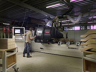
A CNC wood router is a CNC router tool that creates objects from wood. CNC stands for computer numerical control. The CNC works on the Cartesian coordinate system for 3D motion control. Parts of a project can be designed in the computer with a CAD/CAM program, and then cut automatically using a router or other cutters to produce a finished part. The CNC router is ideal for hobbies, engineering prototyping, product development, art, and production work.

Computer-integrated manufacturing Manufacturing controlled by computers

Computer-integrated manufacturing (CIM) is the manufacturing approach of using computers to control entire production process. This integration allows individual processes to exchange information with each part. Manufacturing can be faster and less error-prone by the integration of computers. Typically CIM relies on closed-loop control processes based on real-time input from sensors. It is also known as flexible design and manufacturing.

Modular design, or modularity in design, is a design principle that subdivides a system into smaller parts called modules, which can be independently created, modified, replaced, or exchanged with other modules or between different systems.
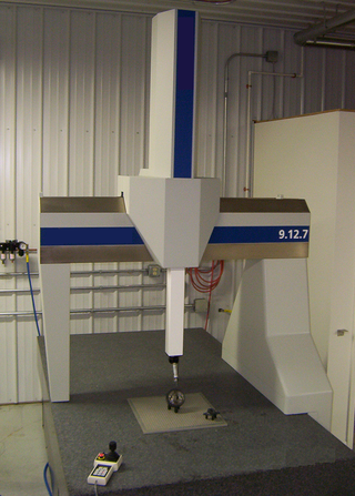
Design for manufacturability Designing products to facilitate manufacturing

Design for manufacturability is the general engineering practice of designing products in such a way that they are easy to manufacture. The concept exists in almost all engineering disciplines, but the implementation differs widely depending on the manufacturing technology. DFM describes the process of designing or engineering a product in order to facilitate the manufacturing process in order to reduce its manufacturing costs. DFM will allow potential problems to be fixed in the design phase which is the least expensive place to address them. Other factors may affect the manufacturability such as the type of raw material, the form of the raw material, dimensional tolerances, and secondary processing such as finishing.

A flexible manufacturing system (FMS) is a manufacturing system in which there is some amount of flexibility that allows the system to react in case of changes, whether predicted or unpredicted.

Tool and die maker Class of machinist in manufacturing

Tool and die makers are highly skilled crafters working in the manufacturing industries. Variations on the name include tool maker,toolmaker, die maker,diemaker, mold maker,moldmaker or tool jig and die-maker depending on which area of concentration or industry an individual works in.

Outline of manufacturing Overview of and topical guide to manufacturing

The following outline is provided as an overview of and topical guide to manufacturing:

A microfactory either refers to a capital-light facility used for the local assembly of a complex product or system or a small factory for producing small quantities of products. The term was proposed by the Mechanical Engineer Laboratory (MEL) of Japan in 1990 and has recently been used to describe the approach of manufacturers like Arrival. The microfactory's main advantages are saving a substantial amount of space, energy, materials, time, and upfront capital costs.

Incremental sheet forming is a sheet metal forming technique where a sheet is formed into the final workpiece by a series of small incremental deformations. However, studies have shown that it can be applied to polymer and composite sheets too. Generally, the sheet is formed by a round tipped tool, typically 5 to 20mm in diameter. The tool, which can be attached to a CNC machine, a robot arm or similar, indents into the sheet by about 1 mm and follows a contour for the desired part. It then indents further and draws the next contour for the part into the sheet and continues to do this until the full part is formed. ISF can be divided into variants depending on the number of contact points between tool, sheet and die. The term Single Point Incremental Forming (SPIF) is used when the opposite side of the sheet is supported by a faceplate and Two Point Incremental Forming (TPIF) when a full or partial die supports the sheet.

Manufacturing engineering Branch of engineering

Manufacturing engineering is a branch of professional engineering that shares many common concepts and ideas with other fields of engineering such as mechanical, chemical, electrical, and industrial engineering. Manufacturing engineering requires the ability to plan the practices of manufacturing; to research and to develop tools, processes, machines and equipment; and to integrate the facilities and systems for producing quality products with the optimum expenditure of capital.

LinuxCNC is a free, open-source Linux software system that implements numerical control capability using general purpose computers to control CNC machines. Designed by various volunteer developers at linuxcnc.org, it is typically bundled as an ISO file with a modified version of 32-bit Ubuntu Linux which provides the required real-time kernel.

A punching machine is a machine tool for punching and embossing flat sheet-materials to produce form-features needed as mechanical element and/or to extend static stability of a sheet section.

Industrial and production engineering (IPE) is an interdisciplinary engineering discipline that includes manufacturing technology, engineering sciences, management science, and optimization of complex processes, systems, or organizations. It is concerned with the understanding and application of engineering procedures in manufacturing processes and production methods. Industrial engineering dates back all the way to the industrial revolution, initiated in 1700s by Sir Adam Smith, Henry Ford, Eli Whitney, Frank Gilbreth and Lilian Gilbreth, Henry Gantt, F.W. Taylor, etc. After the 1970s, industrial and production engineering developed worldwide and started to widely use automation and robotics. Industrial and production engineering includes three areas: Mechanical engineering, industrial engineering, and management science.

Virtual machining is the practice of using computers to simulate and model the use of machine tools for part manufacturing. Such activity replicates the behavior and errors of a real environment in virtual reality systems. This can provide useful ways to manufacture products without physical testing on the shop floor. As a result, time and cost of part production can be decreased.

Yoram Koren Israeli-American engineering academic

Yoram Koren is an Israeli-American academic. He is the James J. Duderstadt Distinguished University Professor Emeritus of Manufacturing and the Paul G. Goebel Professor Emeritus of Engineering at the University of Michigan, Ann Arbor. Since 2014 he is a distinguished visiting professor at the Technion – Israel Institute of Technology.

Learning factories represent a realistic manufacturing environment for education, training, and research. In the last decades, numerous learning factories have been built in academia and industry.

Galip Ulsoy Prof. of mechanical engineering

Ali Galip Ulsoy is an academic at the University of Michigan (UM), Ann Arbor, where he is the C.D. Mote, Jr. Distinguished University Professor Emeritus of Mechanical Engineering and the William Clay Ford Professor Emeritus of Manufacturing.

References

  1. Koren, Y., Jovane, F., Heisel, U., Moriwaki,, T., Pritschow G., Ulsoy G., and VanBrussel H.: Reconfigurable Manufacturing Systems. A Keynote paper. CIRP Annals, Vol. 48, No. 2, pp. 6-12, November 1999.
  2. Michigan Engineering | About our ERC
  3. NSF Grant: Engineering Research Center for Reconfigurable Machining Systems
  4. Kusiak, A. and Lee, G.H., Design of Components and Manufacturing Systems for Reconfigurability, Proceedings of the First World Conference on Integrated Design and Process Technology, Austin, TX, pp. 14-20, December 1995.
  5. 1 2 Koren Y. and Kota, S.: Reconfigurable Machine Tool. US patent US 5943750 ; issue date: 8/31/1999.
  6. 1 2 3 Engineering Research Center for Reconfigurable Machining Systems
  7. 1 2 Koren, Y. and Ulsoy, G,: Reconfigurable Manufacturing System Having a Method for Changing its Production Capacity. US patent # 6,349,237; issue date: 2/19/2002.
  8. 1 2 Landers, R., Min, B.K., and Koren, Y.: Reconfigurable Machine Tools. CIRP Annals, Vol. 49, No. 1, pp. 269-274, July 2001.
  9. Mehrabi, M. Ulsoy, G. and Koren Y.: Reconfigurable Manufacturing Systems: Key to Future Manufacturing. Journal of Intelligent Manufacturing, Vol. 11, No. 4, pp. 403-419, August 2000.
  10. Koren, Y.: Computer Control of Manufacturing Systems. McGraw-Hill Book Co., New York, 1983. ISBN   0-07-035341-7
  11. Koren, Y. and Katz, R.: Reconfigurable Apparatus for Inspection During a Manufacturing Process. US patent # 6,567,162 Issue date: 5/20/03.
  12. Koren, Y., Hu J., and Weber T.: Impact of Manufacturing System Configuration on Performance. CIRP Annals, Vol. 1, pp. 689-698, August 1998.
  13. 1 2 Jianjun Shi, J. Stream of Variation Modeling and Analysis for Multistage Manufacturing Processes. CRC Press, Taylor & Francis Group, 2006. ISBN   0-8493-2151-4.
  14. 1 2 Hu,, S. J. and Koren Y.: Stream of Variation Theory for Automotive Body Assembly. Annals of the CIRP, Vol. 46/1, pp.1-6. 1997.
  15. Hu, S. J. and Koren Y. System Configuration – Reconsider Machine Layout to Optimize Production. Manufacturing Engineering. Vol. 134, No. 2, pp. 81-90. February 2005.
  16. Freiheit T., Koren Y., and Hu S. J.: Productivity of Parallel Production Lines With Unreliable Machines and Material Handling. IEEE Transactions on Automation Science and Engineering, vol. 1, No. 1, pp. 98-103. July 2004
  17. Tang L., Yip-Hoi D., Wang W., and Koren Y.: Concurrent Line-Balancing, Equipment Selection and Throughput Analysis for Multi-Part Optimal Line Design. The International Journal for Manufacturing Science & Production Vol. 6 No. 1, 2004. pp. 71-81.
  18. Tang, L., Yip-Hoi D., Wang W., and Koren Y.: Computer-aided Reconfiguration Planning: An AI-based Approach. ASME Transactions, Journal of Computing & Information Science in Engineering (JCISE). 2006.
  19. Moon, YM and Kota, S.: Design of reconfigurable machine tools. Journal of Manufacturing Science and Engineering, Trans of the ASME, 124:22, pp. 480-483, May 2002.
  20. Shah, SS., Endsley, EW., Lucas, MR, and Tilbury D.: Reconfigurable logic control Proceedings of the American Control Conference, May, 2002.
  21. ERC Achievements Showcase-ERC/RMS Reconfigurable Inspection Machine Installed on GMC Manufacturing Line