Related Research Articles

Analog television is the original television technology that uses analog signals to transmit video and audio. In an analog television broadcast, the brightness, colors and sound are represented by amplitude, phase and frequency of an analog signal.

In electrical engineering, a ground plane is an electrically conductive surface, usually connected to electrical ground. The term has two different meanings in separate areas of electrical engineering. In antenna theory, a ground plane is a conducting surface large in comparison to the wavelength, such as the Earth, which is connected to the transmitter's ground wire and serves as a reflecting surface for radio waves. In printed circuit boards, a ground plane is a large area of copper foil on the board which is connected to the power supply ground terminal and serves as a return path for current from different components on the board.
A PIN diode is a diode with a wide, undoped intrinsic semiconductor region between a p-type semiconductor and an n-type semiconductor region. The p-type and n-type regions are typically heavily doped because they are used for ohmic contacts.
In radio engineering and telecommunications, standing wave ratio (SWR) is a measure of impedance matching of loads to the characteristic impedance of a transmission line or waveguide. Impedance mismatches result in standing waves along the transmission line, and SWR is defined as the ratio of the partial standing wave's amplitude at an antinode (maximum) to the amplitude at a node (minimum) along the line.

A time-domain reflectometer (TDR) is an electronic instrument used to determine the characteristics of electrical lines by observing reflected waveforms.
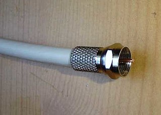
In electrical engineering, a transmission line is a specialized cable or other structure designed to conduct electromagnetic waves in a contained manner. The term applies when the conductors are long enough that the wave nature of the transmission must be taken into account. This applies especially to radio-frequency engineering because the short wavelengths mean that wave phenomena arise over very short distances. However, the theory of transmission lines was historically developed to explain phenomena on very long telegraph lines, especially submarine telegraph cables.
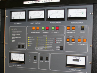
In electronics and telecommunications a transmitter or radio transmitter is an electronic device which produces radio waves with an antenna. The transmitter itself generates a radio frequency alternating current, which is applied to the antenna. When excited by this alternating current, the antenna radiates radio waves.
Demodulation is extracting the original information-bearing signal from a carrier wave. A demodulator is an electronic circuit that is used to recover the information content from the modulated carrier wave. There are many types of modulation so there are many types of demodulators. The signal output from a demodulator may represent sound, images or binary data.

Low-voltage differential signaling, or LVDS, also known as TIA/EIA-644, is a technical standard that specifies electrical characteristics of a differential, serial signaling standard, but it is not a protocol. LVDS operates at low power and can run at very high speeds using inexpensive twisted-pair copper cables. LVDS is a physical layer specification only; many data communication standards and applications use it and add a data link layer as defined in the OSI model on top of it.
This is an index of articles relating to electronics and electricity or natural electricity and things that run on electricity and things that use or conduct electricity.
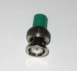
In electronics, electrical termination is the practice of ending a transmission line with a device that matches the characteristic impedance of the line. Termination prevents signals from reflecting off the end of the transmission line. Reflections at the ends of unterminated transmission lines cause distortion which can produce ambiguous digital signal levels and mis-operation of digital systems. Reflections in analog signal systems cause such effects as video ghosting, or power loss in radio transmitter transmission lines.

In radio communications, a radio receiver, also known as a receiver, a wireless or simply a radio, is an electronic device that receives radio waves and converts the information carried by them to a usable form. It is used with an antenna. The antenna intercepts radio waves and converts them to tiny alternating currents which are applied to the receiver, and the receiver extracts the desired information. The receiver uses electronic filters to separate the desired radio frequency signal from all the other signals picked up by the antenna, an electronic amplifier to increase the power of the signal for further processing, and finally recovers the desired information through demodulation.
The Beverage antenna or "wave antenna" is a long-wire receiving antenna mainly used in the low frequency and medium frequency radio bands, invented by Harold H. Beverage in 1921. It is used by amateur radio, shortwave listening, and longwave radio DXers and military applications.

Electronic filters are a type of signal processing filter in the form of electrical circuits. This article covers those filters consisting of lumped electronic components, as opposed to distributed-element filters. That is, using components and interconnections that, in analysis, can be considered to exist at a single point. These components can be in discrete packages or part of an integrated circuit.

Signal integrity or SI is a set of measures of the quality of an electrical signal. In digital electronics, a stream of binary values is represented by a voltage waveform. However, digital signals are fundamentally analog in nature, and all signals are subject to effects such as noise, distortion, and loss. Over short distances and at low bit rates, a simple conductor can transmit this with sufficient fidelity. At high bit rates and over longer distances or through various mediums, various effects can degrade the electrical signal to the point where errors occur and the system or device fails. Signal integrity engineering is the task of analyzing and mitigating these effects. It is an important activity at all levels of electronics packaging and assembly, from internal connections of an integrated circuit (IC), through the package, the printed circuit board (PCB), the backplane, and inter-system connections. While there are some common themes at these various levels, there are also practical considerations, in particular the interconnect flight time versus the bit period, that cause substantial differences in the approach to signal integrity for on-chip connections versus chip-to-chip connections.

The standing wave ratio meter, SWR meter, ISWR meter, or VSWR meter measures the standing wave ratio (SWR) in a transmission line. The meter indirectly measures the degree of mismatch between a transmission line and its load. Electronics technicians use it to adjust radio transmitters and their antennas and feedlines to be impedance matched so they work together properly, and evaluate the effectiveness of other impedance matching efforts.

Parallel SCSI is the earliest of the interface implementations in the SCSI family. SPI is a parallel bus; there is one set of electrical connections stretching from one end of the SCSI bus to the other. A SCSI device attaches to the bus but does not interrupt it. Both ends of the bus must be terminated.

In radio, a detector is a device or circuit that extracts information from a modulated radio frequency current or voltage. The term dates from the first three decades of radio (1888-1918). Unlike modern radio stations which transmit sound on an uninterrupted carrier wave, early radio stations transmitted information by radiotelegraphy. The transmitter was switched on and off to produce long or short periods of radio waves, spelling out text messages in Morse code. Therefore, early radio receivers had only to distinguish between the presence or absence of a radio signal. The device that performed this function in the receiver circuit was called a detector. A variety of different detector devices, such as the coherer, electrolytic detector, magnetic detector and the crystal detector, were used during the wireless telegraphy era until superseded by vacuum tube technology.
On-die termination (ODT) is the technology where the termination resistor for impedance matching in transmission lines is located inside a semiconductor chip instead of on a printed circuit board (PCB).
A signal travelling along an electrical transmission line will be partly, or wholly, reflected back in the opposite direction when the travelling signal encounters a discontinuity in the characteristic impedance of the line, or if the far end of the line is not terminated in its characteristic impedance. This can happen, for instance, if two lengths of dissimilar transmission lines are joined together.
References
This article includes a list of references, related reading or external links, but its sources remain unclear because it lacks inline citations .(March 2008) (Learn how and when to remove this template message) |
- Johnson, Howard; Graham, Martin (1993). High Speed Digital Design. Prentice Hall. ISBN 0-13-395724-1.
- ↑ Anderson, Don; Shanley, Tom; MindShare, Inc (1999). PCI System Architecture. Addison-Wesley Professional. p. 23. ISBN 978-0-201-30974-4 . Retrieved 7 October 2017.