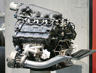
A machine is a physical system using power to apply forces and control movement to perform an action. The term is commonly applied to artificial devices, such as those employing engines or motors, but also to natural biological macromolecules, such as molecular machines. Machines can be driven by animals and people, by natural forces such as wind and water, and by chemical, thermal, or electrical power, and include a system of mechanisms that shape the actuator input to achieve a specific application of output forces and movement. They can also include computers and sensors that monitor performance and plan movement, often called mechanical systems.

Steering is a system of components, linkages, and other parts that allows a driver to control the direction of a vehicle.

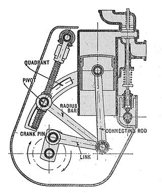
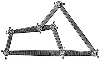
In kinematics, the parallel motion linkage is a six-bar mechanical linkage invented by the Scottish engineer James Watt in 1784 for the double-acting Watt steam engine. It allows a rod moving practically straight up and down to transmit motion to a beam moving in an arc, without putting significant sideways strain on the rod.
In kinematics, Watt's linkage is a type of mechanical linkage invented by James Watt in which the central moving point of the linkage is constrained to travel on a nearly straight line. It was described in Watt's patent specification of 1784 for the Watt steam engine.

In the study of mechanisms, a four-bar linkage, also called a four-bar, is the simplest closed-chain movable linkage. It consists of four bodies, called bars or links, connected in a loop by four joints. Generally, the joints are configured so the links move in parallel planes, and the assembly is called a planar four-bar linkage. Spherical and spatial four-bar linkages also exist and are used in practice.
A mechanical linkage is an assembly of systems connected to manage forces and movement. The movement of a body, or link, is studied using geometry so the link is considered to be rigid. The connections between links are modeled as providing ideal movement, pure rotation or sliding for example, and are called joints. A linkage modeled as a network of rigid links and ideal joints is called a kinematic chain.

The Peaucellier–Lipkin linkage, invented in 1864, was the first true planar straight line mechanism – the first planar linkage capable of transforming rotary motion into perfect straight-line motion, and vice versa. It is named after Charles-Nicolas Peaucellier (1832–1913), a French army officer, and Yom Tov Lipman Lipkin (1846–1876), a Lithuanian Jew and son of the famed Rabbi Israel Salanter.

In kinematics, the Chebyshev Lambda Linkage is a four-bar linkage that converts rotational motion to approximate straight-line motion with approximate constant velocity. It is so-named because it looks like a lowercase Greek letter lambda (λ). The precise design trades off straightness, lack of acceleration, and the proportion of the driving rotation that is spent in the linear portion of the full curve.

A Scott Russell linkage is a linkage which translates linear motion through a right angle.

A straight-line mechanism is a mechanism that converts any type of rotary or angular motion to perfect or near-perfect straight-line motion, or vice versa. Straight-line motion is linear motion of definite length or "stroke", every forward stroke being followed by a return stroke, giving reciprocating motion. The first such mechanism, patented in 1784 by James Watt, produced approximate straight-line motion, referred to by Watt as parallel motion.

The Sarrus linkage, invented in 1853 by Pierre Frédéric Sarrus, is a mechanical linkage to convert a limited circular motion to a linear motion or vice versa without reference guideways. It is a spatial six-bar linkage (6R) with two groups of three parallel adjacent joint-axes.

In kinematics, Chebyshev's linkage is a four-bar linkage that converts rotational motion to approximate linear motion.

In kinematics, cognate linkages are linkages that ensure the same coupler curve geometry or input-output relationship, while being dimensionally dissimilar. In case of four-bar linkage coupler cognates, the Roberts–Chebyshev Theorem, after Samuel Roberts and Pafnuty Chebyshev, states that each coupler curve can be generated by three different four-bar linkages. These four-bar linkages can be constructed using similar triangles and parallelograms, and the Cayley diagram.

The Klannlinkage is a planar mechanism designed to simulate the gait of legged animal and function as a wheel replacement, a leg mechanism. The linkage consists of the frame, a crank, two grounded rockers, and two couplers all connected by pivot joints. It was developed by Joe Klann in 1994 as an expansion of Burmester curves which are used to develop four-bar double-rocker linkages such as harbor crane booms. It is categorized as a modified Stephenson type III kinematic chain.

In engineering, a mechanism is a device that transforms input forces and movement into a desired set of output forces and movement. Mechanisms generally consist of moving components which may include:
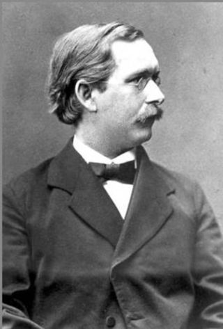
Ludwig Ernst Hans Burmester was a German kinematician and geometer.
In mechanics, a six-bar linkage is a mechanism with one degree of freedom that is constructed from six links and seven joints. An example is the Klann linkage used to drive the legs of a walking machine.
A dwell mechanism is an intermittent motion mechanism that alternates forward and return motion with holding position(s).

In kinematics, the Hoecken linkage is a four-bar linkage that converts rotational motion to approximate straight-line motion. The Hoecken linkage is a cognate linkage of the Chebyshev linkage and Chebyshev's Lambda Mechanism.

A slider-crank linkage is a four-link mechanism with three revolute joints and one prismatic, or sliding, joint. The rotation of the crank drives the linear movement of the slider, or the expansion of gases against a sliding piston in a cylinder can drive the rotation of the crank.
