Record
field | Record
purpose | Address
field | Data
field | Record
description |
|---|
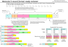
| S0 | Header | — |  | The data field in this record type may be empty, or may contain the hex equivalent of application-specific ASCII information, often in the form of a null-terminated string. [3] In lieu of more specific information, it is common to see 48, 44, 52, which is the ASCII representation of the letters "HDR". [4] The address field will always contain the hex representation of $0000 ($ indicates a hexadecimal number in Motorola 6800 assembly language). |
| S1 | Data | 16-bit
address | | The data field in this record type contains data that is loaded to the 16-bit address in the address field. [3] [4] [5] The number of bytes of data contained in this record is "Byte Count Field" minus 3 (2 bytes for "16-bit Address Field" plus 1 byte for "Checksum Field"). This record type is typically used with eight-bit processors, such as the 6502 and 6800 families, the 8051, the Z80, the AVR and PIC. |
| S2 | Data | 24-bit
address | | The data field in this record type contains data that is loaded to the 24-bit address in the address field. [3] [4] The number of bytes of data contained in this record is "Byte Count Field" minus 4 (3 bytes for "24-bit Address Field" plus 1 byte for "Checksum Field"). The S2 record type was added by Motorola to support the MC68000 microprocessor, which has a 24-bit address bus. [3] This record type is also usable with the Western Design Center 65C816, which emits 24-bit addresses. |
| S3 | Data | 32-bit
address | | The data field in this record type contains data that is loaded to the 32-bit address in the address field. [3] [4] The number of bytes of data contained in this record is "Byte Count Field" minus 5 (4 bytes for "32-bit Address Field" plus 1 byte for "Checksum Field"). The S3 record type was added to support the 68012 and later 68000-series microprocessors that are equipped with a 32-bit data bus. [3] This record type is also usable with non-Motorola 32-bit processors, such as the ARM architecture family and the RISC-V. |
| S4 | Undefined | — | — | This record type is not defined by the official S-record standard. [3] |
| S5 | Count | 16-bit
count |  | This optional record type contains a 16-bit count of S1/S2/S3 records that have been transmitted. The data field is not used. [3] [4] |
| S6 | Non-standard | 24-bit
count | | This record type is not defined by the official S-record standard. [3] However, some applications treat this record as an optional 24-bit count of S1/S2/S3 records that have been transmitted. [4] In such an application, the data field is not used. |
| S7 | Start address
(termination) | 32-bit
address | | This record type contains an optional 32-bit address that is the entry point for program execution. [3] [4] An address of $00000000 is used if no specific address is required, such as when S-records are used to burn EPROMs and the like. This record type is used to terminate a series of S3 records. [3] The data field is not used. |
| S8 | Start address
(termination) | 24-bit
address | | This record type contains an optional 24-bit address that is the entry point for program execution. [3] [4] An address of $000000 is used if no specific address is required. This record type is used to terminate a series of S2 records. [3] The data field is not used. |
| S9 | Start address
(termination) | 16-bit
address | | This record type contains an optional 16-bit address that is the entry point for program execution. [3] [4] An address of $0000 is used if no specific address is required. This record type is used to terminate a series of S1 records. [3] The data field is not used. |