Related Research Articles

An electromagnetic coil is an electrical conductor such as a wire in the shape of a coil. Electromagnetic coils are used in electrical engineering, in applications where electric currents interact with magnetic fields, in devices such as electric motors, generators, inductors, electromagnets, transformers, sensor coils such as in medical FMRi imaging devices with coils going upto 3-7 and even higher Tesla. Either an electric current is passed through the wire of the coil to generate a magnetic field, or conversely, an external time-varying magnetic field through the interior of the coil generates an EMF (voltage) in the conductor.

In electrical engineering, a transformer is a passive component that transfers electrical energy from one electrical circuit to another circuit, or multiple circuits. A varying current in any coil of the transformer produces a varying magnetic flux in the transformer's core, which induces a varying electromotive force (EMF) across any other coils wound around the same core. Electrical energy can be transferred between separate coils without a metallic (conductive) connection between the two circuits. Faraday's law of induction, discovered in 1831, describes the induced voltage effect in any coil due to a changing magnetic flux encircled by the coil.

In electrical engineering, ground or earth may be a reference point in an electrical circuit from which voltages are measured, a common return path for electric current, or a direct physical connection to the Earth.

An electric motor is an electrical machine that converts electrical energy into mechanical energy. Most electric motors operate through the interaction between the motor's magnetic field and electric current in a wire winding to generate force in the form of torque applied on the motor's shaft. An electric generator is mechanically identical to an electric motor, but operates in reverse, converting mechanical energy into electrical energy.

A commutator is a rotary electrical switch in certain types of electric motors and electrical generators that periodically reverses the current direction between the rotor and the external circuit. It consists of a cylinder composed of multiple metal contact segments on the rotating armature of the machine. Two or more electrical contacts called "brushes" made of a soft conductive material like carbon press against the commutator, making sliding contact with successive segments of the commutator as it rotates. The windings on the armature are connected to the commutator segments.
In electrical engineering, partial discharge (PD) is a localized dielectric breakdown (DB) of a small portion of a solid or fluid electrical insulation (EI) system under high voltage (HV) stress. While a corona discharge (CD) is usually revealed by a relatively steady glow or brush discharge (BD) in air, partial discharges within solid insulation system are not visible.

A synchronous electric motor is an AC electric motor in which, at steady state, the rotation of the shaft is synchronized with the frequency of the supply current; the rotation period is exactly equal to an integer number of AC cycles. Synchronous motors use electromagnets as the stator of the motor which create a magnetic field that rotates in time with the oscillations of the current. The rotor with permanent magnets or electromagnets turns in step with the stator field at the same rate and as a result, provides the second synchronized rotating magnet field. A synchronous motor is termed doubly fed if it is supplied with independently excited multiphase AC electromagnets on both the rotor and stator.
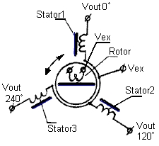
A synchro is, in effect, a transformer whose primary-to-secondary coupling may be varied by physically changing the relative orientation of the two windings. Synchros are often used for measuring the angle of a rotating machine such as an antenna platform or transmitting rotation. In its general physical construction, it is much like an electric motor. The primary winding of the transformer, fixed to the rotor, is excited by an alternating current, which by electromagnetic induction causes voltages to appear between the Y-connected secondary windings fixed at 120 degrees to each other on the stator. The voltages are measured and used to determine the angle of the rotor relative to the stator.

A DC motor is an electrical motor that uses direct current (DC) to produce mechanical force. The most common types rely on magnetic forces produced by currents in the coils. Nearly all types of DC motors have some internal mechanism, either electromechanical or electronic, to periodically change the direction of current in part of the motor.

A current transformer (CT) is a type of transformer that is used to reduce or multiply an alternating current (AC). It produces a current in its secondary which is proportional to the current in its primary.
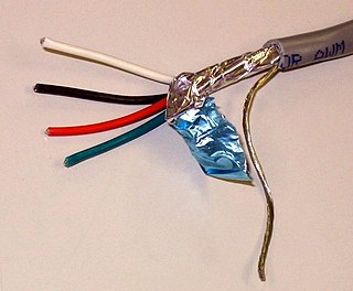
A shielded cable or screened cable is an electrical cable that has a common conductive layer around its conductors for electromagnetic shielding. This shield is usually covered by an outermost layer of the cable. Common types of cable shielding can most broadly be categorized as foil type, contraspiralling wire strands or both. A longitudinal wire may be necessary with dielectric spiral foils to short out each turn.

A variable-frequency drive is a type of AC motor drive that controls speed and torque by varying the frequency of the input electricity. Depending on its topology, it controls the associated voltage or current variation.
This is an alphabetical list of articles pertaining specifically to electrical and electronics engineering. For a thematic list, please see List of electrical engineering topics. For a broad overview of engineering, see List of engineering topics. For biographies, see List of engineers.

Motor drive means a system that includes a motor. An adjustable speed motor drive means a system that includes a motor that has multiple operating speeds. A variable speed motor drive is a system that includes a motor and is continuously variable in speed. If the motor is generating electrical energy rather than using it – this could be called a generator drive but is often still referred to as a motor drive.

An AC motor is an electric motor driven by an alternating current (AC). The AC motor commonly consists of two basic parts, an outside stator having coils supplied with alternating current to produce a rotating magnetic field, and an inside rotor attached to the output shaft producing a second rotating magnetic field. The rotor magnetic field may be produced by permanent magnets, reluctance saliency, or DC or AC electrical windings.
Doubly fed electric machines, also slip-ring generators, are electric motors or electric generators, where both the field magnet windings and armature windings are separately connected to equipment outside the machine.

The rotor is a moving component of an electromagnetic system in the electric motor, electric generator, or alternator. Its rotation is due to the interaction between the windings and magnetic fields which produces a torque around the rotor's axis.

A dynamo is an electrical generator that creates direct current using a commutator. Dynamos were the first electrical generators capable of delivering power for industry, and the foundation upon which many other later electric-power conversion devices were based, including the electric motor, the alternating-current alternator, and the rotary converter.

A variety of types of electrical transformer are made for different purposes. Despite their design differences, the various types employ the same basic principle as discovered in 1831 by Michael Faraday, and share several key functional parts.
This glossary of electrical and electronics engineering is a list of definitions of terms and concepts related specifically to electrical engineering and electronics engineering. For terms related to engineering in general, see Glossary of engineering.
References
- ↑ Hamid A. Toliyat, G. B. Kliman Handbook of electric motors CRC Press, 2004 ISBN 0824741056, pp.672-688
- ↑ "Turning The Tables On Shaft Voltage And Bearing Currents", David W. Schlegel, Russel J. Kerkman, and Gary L. Skibinski, Electrical Construction & Maintenance (EC&M) Magazine, June 1998,
- ↑ "How to Select a VFD", John Yoon (PE, LEED AP), Consulting-Specifying Engineer, November 2010,
- ↑ Shaft grounding. A solution to motor bearing currents
- ↑ "Control Engineering".
- 1 2 Are Bearing Currents Causing Your Motor Failures? Greenheck
- ↑ Busse, D.F.; Erdman, J.M.; Kerkman, R.J.; Schlegel, D.W.; Skibinski, G.L. (1997). "An evaluation of the electrostatic shielded induction motor: A solution for rotor shaft voltage buildup and bearing current". IEEE Transactions on Industry Applications. 33 (6): 1563–1570. doi:10.1109/28.649969.
- ↑ "Shaft Grounding Systems" (PDF). Retrieved 30 March 2023.