Spatial filter

Last updated

A spatial filter is an optical device which uses the principles of Fourier optics to alter the structure of a beam of light or other electromagnetic radiation, typically coherent laser light. Spatial filtering is commonly used to "clean up" the output of lasers, removing aberrations in the beam due to imperfect, dirty, or damaged optics, or due to variations in the laser gain medium itself. This filtering can be applied to transmit a pure transverse mode from a multimode laser while blocking other modes emitted from the optical resonator. [1] [2] The term "filtering" indicates that the desirable structural features of the original source pass through the filter, while the undesirable features are blocked. An apparatus which follows the filter effectively sees a higher-quality but lower-powered image of the source, instead of the actual source directly. An example of the use of spatial filter can be seen in advanced setup of micro-Raman spectroscopy.

Contents

A computer-generated example of an Airy disk, point-source diffraction pattern. Airy-pattern.svg
A computer-generated example of an Airy disk, point-source diffraction pattern.

In spatial filtering, a lens is used to focus the beam. Because of diffraction, a beam that is not a perfect plane wave will not focus to a single spot, but rather will produce a pattern of light and dark regions in the focal plane. For example, an imperfect beam might form a bright spot surrounded by a series of concentric rings, as shown in the figure to the right. It can be shown that this two-dimensional pattern is the two-dimensional Fourier transform of the initial beam's transverse intensity distribution. In this context, the focal plane is often called the transform plane. Light in the very center of the transform pattern corresponds to a perfect, wide plane wave. Other light corresponds to "structure" in the beam, with light further from the central spot corresponding to structure with higher spatial frequency . A pattern with very fine details will produce light very far from the transform plane's central spot. In the example above, the large central spot and rings of light surrounding it are due to the structure resulting when the beam passed through a circular aperture. The spot is enlarged because the beam is limited by the aperture to a finite size, and the rings relate to the sharp edges of the beam created by the edges of the aperture. This pattern is called an Airy pattern, after its discoverer George Airy.

By altering the distribution of light in the transform plane and using another lens to reform the collimated beam, the structure of the beam can be altered. The most common way of doing this is to place an aperture in the beam that allows the desired light to pass, while blocking light that corresponds to undesired structure in the beam. In particular, a small circular aperture or "pinhole" that passes only the central bright spot can remove nearly all fine structure from the beam, producing a smooth transverse intensity profile, which may be almost a perfect gaussian beam. With good optics and a very small pinhole, one could even approximate a plane wave.

In practice, the diameter of the aperture is chosen based on the focal length of the lens, the diameter and quality of the input beam, and its wavelength (longer wavelengths require larger apertures). If the hole is too small, the beam quality is greatly improved but the power is greatly reduced. If the hole is too large, the beam quality may not be improved as much as desired.

The size of aperture that can be used also depends on the size and quality of the optics. To use a very small pinhole, one must use a focusing lens with a low f-number, and ideally the lens should not add significant aberrations to the beam. The design of such a lens becomes increasingly more difficult as the f-number decreases.

In practice, the most commonly used configuration is to use a microscope objective lens for focusing the beam, and an aperture made by punching a small, precise, hole in a piece of thick metal foil. Such assemblies are available commercially.

Spatial Filter for Image Enhancement

Digital images have an important role in our life. Digital imaging has a wide range of applications in many research areas, such as medical sciences, biology, particle physics, geology, the science of materials, photography and remote sensing. For some medical practices, digital imaging plays an important role, especially for studying physiology abnormalities and anatomy of the internal organs. Countless images are made, translated and edited daily.

However, many images that are created have some imperfections called noise. Such imperfections may be caused by the incapacity and instability of imaging systems or sensors to obtain ideal images, or natural disruptions in the surroundings during image processing, inadequate illumination, or sensor temperature resulting in noise, or during compression and transmission. Data obtained with these noises can make the data unusable or lose confidence in them.

An essential method in image processing for enhancing or changing a picture's qualities is spatial filtering. It modifies pixel values directly in the spatial domain of the image by taking into account the values of nearby pixels. Digital photography, medical imaging, remote sensing, computer vision, and other areas all make extensive use of this approach.

Spatial filtering is essentially the process of convolutioning an image using a filter matrix or kernel. The action to be carried out on each pixel and its neighbours is defined by the kernel, which is usually a tiny square or rectangle matrix. Sliding the kernel over the image, adding up the weights of each pixel at each location, and then swapping out the result for the central pixel value is the convolution process. A common term for this weighted total is the "filter response."

Different uses for spatial filters may be achieved based on their characteristics and design. picture sharpening, picture blurring, edge detection, and noise reduction are common uses. An edge detection filter, for instance, identifies areas of abrupt intensity change, whereas a smoothing filter blurs a picture by averaging the values of nearby pixels.

Techniques for spatial filtering might be either nonlinear or linear. Because they are simple to use and economical, linear filters calculate the output pixel value as a linear combination of the input pixel values. On the other hand, nonlinear filters employ more intricate processes, frequently requiring rank ordering or thresholding of pixel values, enabling more intricate picture changes.

Spatial filtering has the benefit of being able to process pictures locally, which makes it appropriate for parallel processing architectures and computationally economical for real-time applications. Furthermore, spatial filtering is flexible and may be tailored to certain imaging requirements by varying the kernel's size and coefficients.

To sum up, spatial filtering is an effective technique for manipulating and enhancing photos. It provides a versatile framework for obtaining significant information from digital images. Its extensive application highlights how important it is in many fields where picture analysis and interpretation are essential.

Spherical waves

By omitting the second lens that reforms the collimated beam, the filter aperture closely approximates an intense point source, which produces light that approximates a spherical wavefront. A smaller aperture implements a closer approximation of a point source, which in turn produces a more nearly spherical wavefront.

See also

Related Research Articles

<span class="mw-page-title-main">Microscopy</span> Viewing of objects which are too small to be seen with the naked eye

Microscopy is the technical field of using microscopes to view objects and areas of objects that cannot be seen with the naked eye. There are three well-known branches of microscopy: optical, electron, and scanning probe microscopy, along with the emerging field of X-ray microscopy.

<span class="mw-page-title-main">Aperture</span> Hole or opening through which light travels

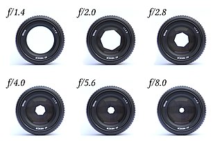
In optics, the aperture of an optical system is a hole or an opening that primarily limits light propagated through the system. More specifically, the entrance pupil as the front side image of the aperture and focal length of an optical system determine the cone angle of a bundle of rays that comes to a focus in the image plane.

<span class="mw-page-title-main">Camera lens</span> Optical lens or assembly of lenses used with a camera to create images

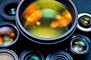
A camera lens is an optical lens or assembly of lenses used in conjunction with a camera body and mechanism to make images of objects either on photographic film or on other media capable of storing an image chemically or electronically.

<span class="mw-page-title-main">Adaptive optics</span> Technique used in optical systems

Adaptive optics (AO) is a technique of precisely deforming a mirror in order to compensate for light distortion. It is used in astronomical telescopes and laser communication systems to remove the effects of atmospheric distortion, in microscopy, optical fabrication and in retinal imaging systems to reduce optical aberrations. Adaptive optics works by measuring the distortions in a wavefront and compensating for them with a device that corrects those errors such as a deformable mirror or a liquid crystal array.

<span class="mw-page-title-main">Diffraction-limited system</span> Optical system with resolution performance at the instruments theoretical limit

In optics, any optical instrument or system – a microscope, telescope, or camera – has a principal limit to its resolution due to the physics of diffraction. An optical instrument is said to be diffraction-limited if it has reached this limit of resolution performance. Other factors may affect an optical system's performance, such as lens imperfections or aberrations, but these are caused by errors in the manufacture or calculation of a lens, whereas the diffraction limit is the maximum resolution possible for a theoretically perfect, or ideal, optical system.

<span class="mw-page-title-main">Point spread function</span> Response in an optical imaging system

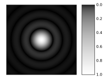
The point spread function (PSF) describes the response of a focused optical imaging system to a point source or point object. A more general term for the PSF is the system's impulse response; the PSF is the impulse response or impulse response function (IRF) of a focused optical imaging system. The PSF in many contexts can be thought of as the extended blob in an image that represents a single point object, that is considered as a spatial impulse. In functional terms, it is the spatial domain version of the optical transfer function (OTF) of an imaging system. It is a useful concept in Fourier optics, astronomical imaging, medical imaging, electron microscopy and other imaging techniques such as 3D microscopy and fluorescence microscopy.

Particle image velocimetry (PIV) is an optical method of flow visualization used in education and research. It is used to obtain instantaneous velocity measurements and related properties in fluids. The fluid is seeded with tracer particles which, for sufficiently small particles, are assumed to faithfully follow the flow dynamics. The fluid with entrained particles is illuminated so that particles are visible. The motion of the seeding particles is used to calculate speed and direction of the flow being studied.

<span class="mw-page-title-main">Confocal microscopy</span> Optical imaging technique

Confocal microscopy, most frequently confocal laser scanning microscopy (CLSM) or laser scanning confocal microscopy (LSCM), is an optical imaging technique for increasing optical resolution and contrast of a micrograph by means of using a spatial pinhole to block out-of-focus light in image formation. Capturing multiple two-dimensional images at different depths in a sample enables the reconstruction of three-dimensional structures within an object. This technique is used extensively in the scientific and industrial communities and typical applications are in life sciences, semiconductor inspection and materials science.

Cone tracing and beam tracing are a derivative of the ray tracing algorithm that replaces rays, which have no thickness, with thick rays.

Optical resolution describes the ability of an imaging system to resolve detail, in the object that is being imaged. An imaging system may have many individual components, including one or more lenses, and/or recording and display components. Each of these contributes to the optical resolution of the system; the environment in which the imaging is done often is a further important factor.

<span class="mw-page-title-main">Image noise</span> Visible interference in an image

Image noise is random variation of brightness or color information in images, and is usually an aspect of electronic noise. It can be produced by the image sensor and circuitry of a scanner or digital camera. Image noise can also originate in film grain and in the unavoidable shot noise of an ideal photon detector. Image noise is an undesirable by-product of image capture that obscures the desired information. Typically the term “image noise” is used to refer to noise in 2D images, not 3D images.

<span class="mw-page-title-main">Apodization</span> Function in signal processing

In signal processing, apodization is the modification of the shape of a mathematical function. The function may represent an electrical signal, an optical transmission, or a mechanical structure. In optics, it is primarily used to remove Airy disks caused by diffraction around an intensity peak, improving the focus.

<span class="mw-page-title-main">Optical transfer function</span> Function that specifies how different spatial frequencies are captured by an optical system

The optical transfer function (OTF) of an optical system such as a camera, microscope, human eye, or projector specifies how different spatial frequencies are captured or transmitted. It is used by optical engineers to describe how the optics project light from the object or scene onto a photographic film, detector array, retina, screen, or simply the next item in the optical transmission chain. A variant, the modulation transfer function (MTF), neglects phase effects, but is equivalent to the OTF in many situations.

The following are common definitions related to the machine vision field.

<span class="mw-page-title-main">Argus laser</span>

Argus was a two-beam high power infrared neodymium doped silica glass laser with a 20 cm (7.9 in) output aperture built at Lawrence Livermore National Laboratory in 1976 for the study of inertial confinement fusion. Argus advanced the study of laser-target interaction and paved the way for the construction of its successor, the 20 beam Shiva laser.

<span class="mw-page-title-main">Laser beam profiler</span> Measurement device

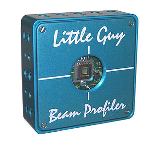
A laser beam profiler captures, displays, and records the spatial intensity profile of a laser beam at a particular plane transverse to the beam propagation path. Since there are many types of lasers—ultraviolet, visible, infrared, continuous wave, pulsed, high-power, low-power—there is an assortment of instrumentation for measuring laser beam profiles. No single laser beam profiler can handle every power level, pulse duration, repetition rate, wavelength, and beam size.

Speckle, speckle pattern, or speckle noise is a granular noise texture degrading the quality as a consequence of interference among wavefronts in coherent imaging systems, such as radar, synthetic aperture radar (SAR), medical ultrasound and optical coherence tomography. Speckle is not external noise; rather, it is an inherent fluctuation in diffuse reflections, because the scatterers are not identical for each cell, and the coherent illumination wave is highly sensitive to small variations in phase changes.

The study of image formation encompasses the radiometric and geometric processes by which 2D images of 3D objects are formed. In the case of digital images, the image formation process also includes analog to digital conversion and sampling.

<span class="mw-page-title-main">Pinhole (optics)</span>

A pinhole is a small circular hole, as could be made with the point of a pin. In optics, pinholes with diameter between a few micrometers and a hundred micrometers are used as apertures in optical systems. Pinholes are commonly used to spatially filter a beam, where the small pinhole acts as a low-pass filter for spatial frequencies in the image plane of the beam.

Computational imaging is the process of indirectly forming images from measurements using algorithms that rely on a significant amount of computing. In contrast to traditional imaging, computational imaging systems involve a tight integration of the sensing system and the computation in order to form the images of interest. The ubiquitous availability of fast computing platforms, the advances in algorithms and modern sensing hardware is resulting in imaging systems with significantly enhanced capabilities. Computational Imaging systems cover a broad range of applications include computational microscopy, tomographic imaging, MRI, ultrasound imaging, computational photography, Synthetic Aperture Radar (SAR), seismic imaging etc. The integration of the sensing and the computation in computational imaging systems allows for accessing information which was otherwise not possible. For example:

References

  1. "Understanding Spatial Filters". Edmund Optics website. Edmund Optics. Retrieved 13 January 2014.
  2. "Spatial Filters". Newport website. Newport. Retrieved 13 January 2014.

[1]

  1. Mursal, Ali Salim Nasar; Ibrahim, Haidi (2020-12-01). "Median Filtering Using First-Order and Second-Order Neighborhood Pixels to Reduce Fixed Value Impulse Noise from Grayscale Digital Images". Electronics. 9 (12): 2034. doi: 10.3390/electronics9122034 . ISSN   2079-9292.