Spiral bevel gear

Last updated
Spiral bevel gear Gear-kegelzahnrad.svg
Spiral bevel gear

A spiral bevel gear is a bevel gear with helical teeth. The main application of this is in a vehicle differential, where the direction of drive from the drive shaft must be turned 90 degrees to drive the wheels. The helical design produces less vibration and noise than conventional straight-cut or spur-cut gear with straight teeth.

Contents

A spiral bevel gear set should always be replaced in pairs i.e. both the left hand and right hand gears should be replaced together since the gears are manufactured and lapped in pairs.

Handedness

Spiral bevel handedness Spiral hand.jpg
Spiral bevel handedness
Zerol handedness Zerol hand.jpg
Zerol handedness

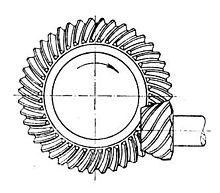
A right hand spiral bevel gear is one in which the outer half of a tooth is inclined in the clockwise direction from the axial plane through the midpoint of the tooth as viewed by an observer looking at the face of the gear.

A left hand spiral bevel gear is one in which the outer half of a tooth is inclined in the counterclockwise direction from the axial plane through the midpoint of the tooth as viewed by an observer looking at the face of the gear.

Note that a spiral bevel gear and pinion are always of opposite hand, including the case when the gear is internal.

Also note that the designations right hand and left hand are applied similarly to other types of bevel gear, hypoid gears, and oblique tooth face gears. [1]

Hypoid gears

Hypoid spiral bevel gears Sprocket35b.jpg
Hypoid spiral bevel gears

A hypoid is a type of spiral bevel gear whose axis does not intersect with the axis of the meshing gear. The shape of a hypoid gear is a revolved hyperboloid (that is, the pitch surface of the hypoid gear is a hyperbolic surface), whereas the shape of a spiral bevel gear is normally conical. The hypoid gear places the pinion off-axis to the crown wheel (ring gear) which allows the pinion to be larger in diameter and have more contact area. In hypoid gear design, the pinion and gear are practically always of opposite hand, and the spiral angle of the pinion is usually larger than that of the gear. The hypoid pinion is then larger in diameter than an equivalent bevel pinion.

A hypoid gear incorporates some sliding and can be considered halfway between a straight-cut gear and a worm gear. Special gear oils are required for hypoid gears because the sliding action requires effective lubrication under extreme pressure between the teeth.

Hypoid gearings are used in power transmission products that are more efficient than conventional worm gearing.[ citation needed ] They are considerably stronger in that any load is conveyed through multiple teeth simultaneously. By contrast, bevel gears are loaded through one tooth at a time. The multiple contacts of hypoid gearing, with proper lubrication, can be nearly silent, as well.

Spiral angle

Spiral angle Spiral angle.jpg
Spiral angle

The spiral angle in a spiral bevel gear is the angle between the tooth trace and an element of the pitch cone, and corresponds to the helix angle in helical teeth. Unless otherwise specified, the term spiral angle is understood to be the mean spiral angle.

Spiral angle relationships Spiral relationships.jpg
Spiral angle relationships

Comparison of spiral bevel gears to hypoid gears

Hypoid gears are stronger, operate more quietly and can be used for higher reduction ratios, however they also have some sliding action along the teeth, which reduces mechanical efficiency, the energy losses being in the form of heat produced in the gear surfaces and the lubricating fluid.

Hypoid gears are typically used in rear-drive automobile drivetrains.

A higher hypoid offset allows the gear to transmit higher torque. However increasing the hypoid offset results in reduction of mechanical efficiency and a consequent reduction in fuel economy. For practical purposes, it is often impossible to replace low efficiency hypoid gears with more efficient spiral bevel gears in automotive use because the spiral bevel gear would need a much larger diameter to transmit the same torque. Increasing the size of the drive axle gear would require an increase of the size of the gear housing and a reduction in the ground clearance, interior space, and an increase in weight.

The hypoid gear is also commonly used in some railcar transmissions with diesel power units - where the engine and gearbox are similar to those used in traditional trucks and busses (not diesel/electric hybrid type drive). The transmission, to allow the input shaft to always rotate in one specific direction (either clockwise or anti-clockwise) while allowing the output shafts to change their rotational direction; thus allowing a vehicle to drive either direction.[ clarification needed ]

Another advantage of hypoid gear is that the ring gear of the differential and the input pinion gear are both hypoid. In most passenger cars this allows the pinion to be offset to the bottom of the crown wheel. This provides for longer tooth contact and allows the shaft that drives the pinion to be lowered, reducing the "hump" intrusion in the passenger compartment floor. However, the greater the displacement of the input shaft axis from the crown wheel axis, the lower the mechanical efficiency.

See also

Related Research Articles

<span class="mw-page-title-main">Gear</span> Rotating circular machine part with teeth that mesh with another toothed part

A gear is a rotating circular machine part having cut teeth or, in the case of a cogwheel or gearwheel, inserted teeth, which mesh with another (compatible) toothed part to transmit rotational power. While doing so, they can change the torque and rotational speed being transmitted and also change the rotational axis of the power being transmitted. The teeth on the two meshing gears all have the same shape.

<span class="mw-page-title-main">Differential (mechanical device)</span> Type of simple planetary gear train

A differential is a gear train with three drive shafts that has the property that the rotational speed of one shaft is the average of the speeds of the others. A common use of differentials is in motor vehicles, to allow the wheels at each end of a drive axle to rotate at different speeds while cornering. Other uses include clocks and analog computers. Differentials can also provide a gear ratio between the input and output shafts. For example, many differentials in motor vehicles provide a gearing reduction by having fewer teeth on the pinion than the ring gear.

<span class="mw-page-title-main">Rack and pinion</span> Type of linear actuator

A rack and pinion is a type of linear actuator that comprises a circular gear engaging a linear gear. Together, they convert between rotational motion and linear motion. Rotating the pinion causes the rack to be driven in a line. Conversely, moving the rack linearly will cause the pinion to rotate. A rack-and-pinion drive can use both straight and helical gears. Though some suggest helical gears are quieter in operation, no hard evidence supports this theory. Helical racks, while being more affordable, have proven to increase side torque on the datums, increasing operating temperature leading to premature wear. Straight racks require a lower driving force and offer increased torque and speed per fraction of gear ratio which allows lower operating temperature and lessens viscal friction and energy use. The maximum force that can be transmitted in a rack-and-pinion mechanism is determined by the torque on the pinion and its size, or, conversely, by the force on the rack and the size of the pinion.

<span class="mw-page-title-main">Involute gear</span> Gear with teeth whose profile is an involute of a circle

The involute gear profile is the most commonly used system for gearing today, with cycloid gearing still used for some specialties such as clocks. In an involute gear, the profiles of the teeth are involutes of a circle. The involute of a circle is the spiraling curve traced by the end of an imaginary taut string unwinding itself from that stationary circle called the base circle, or (equivalently) a triangle wave projected on the circumference of a circle.

<span class="mw-page-title-main">Hobbing</span> Process used to cut teeth into gears

Hobbing is a machining process for gear cutting, cutting splines, and cutting sprockets using a hobbing machine, a specialized milling machine. The teeth or splines of the gear are progressively cut into the material by a series of cuts made by a cutting tool called a hob.

<span class="mw-page-title-main">Epicyclic gearing</span> Two gears mounted so the center of one gear revolves around the center of the other

An epicyclic gear train is a gear reduction assembly consisting of two gears mounted so that the center of one gear revolves around the center of the other. A carrier connects the centers of the two gears and rotates, to carry the planet gear(s) around the sun gear. The planet and sun gears mesh so that their pitch circles roll without slip. If the sun gear is held fixed, then a point on the pitch circle of the planet gear traces an epicycloid curve.

<span class="mw-page-title-main">Manual transmission</span> Motor vehicle manual gearbox; stick shift

A manual transmission (MT), also known as manual gearbox, standard transmission, or stick shift, is a multi-speed motor vehicle transmission system, where gear changes require the driver to manually select the gears by operating a gear stick and clutch.

<span class="mw-page-title-main">Gear oil</span> Lubricant used in vehicles and machinery

Gear oil is a lubricant made specifically for transmissions, transfer cases, and differentials in automobiles, trucks, and other machinery. It has high viscosity and usually contains organosulfur compounds. Some modern automatic transaxles do not use a heavy oil at all but lubricate with the lower viscosity hydraulic fluid, which is available at pressure within the automatic transmission. Gear oils account for about 20% of the lubricant market.

<span class="mw-page-title-main">Shaft-driven bicycle</span> Type of bicycle which uses a drive shaft to transmit power instead of a chain

A shaft-driven bicycle is a bicycle that uses a drive shaft instead of a chain to transmit power from the pedals to the wheel. Shaft drives were introduced in the 1880s, but were mostly supplanted by chain-driven bicycles due to the gear ranges possible with sprockets and derailleurs. Around the 2000s, due to advancements in internal gear technology, a small number of modern shaft-driven bicycles have been introduced.

<span class="mw-page-title-main">Gear train</span> Mechanical transmission using multiple gears

A gear train or gear set is a machine element of a mechanical system formed by mounting two or more gears on a frame such that the teeth of the gears engage.

<span class="mw-page-title-main">Worm drive</span> Gear arrangement


A worm drive is a gear arrangement in which a worm meshes with a worm wheel. The two elements are also called the worm screw and worm gear. The terminology is often confused by imprecise use of the term worm gear to refer to the worm, the worm wheel, or the worm drive as a unit.

<span class="mw-page-title-main">Cycloidal drive</span> Eccentric gear reduction mechanism

A cycloidal drive or cycloidal speed reducer is a mechanism for reducing the speed of an input shaft by a certain ratio. Cycloidal speed reducers are capable of relatively high ratios in compact sizes with very low backlash.

<span class="mw-page-title-main">Bevel gear</span> Cone- or frustum-shaped gears for shafts whose axes intersect

Bevel gears are gears where the axes of the two shafts intersect and the tooth-bearing faces of the gears themselves are conically shaped. Bevel gears are most often mounted on shafts that are 90 degrees apart, but can be designed to work at other angles as well. The pitch surface of bevel gears is a cone, known as a pitch cone. Bevel gears change the axis of rotation of rotational power delivery and are widely used in mechanical settings.

<span class="mw-page-title-main">Reduction drive</span> Mechanical device to shift rotational speed

A reduction drive is a mechanical device to shift rotational speed. A planetary reduction drive is a small scale version using ball bearings in an epicyclic arrangement instead of toothed gears.

Gear cutting is any machining process for creating a gear. The most common gear-cutting processes include hobbing, broaching, milling, grinding, and skiving. Such cutting operations may occur either after or instead of forming processes such as forging, extruding, investment casting, or sand casting.

<span class="mw-page-title-main">Backlash (engineering)</span> Clearance between mating components

In mechanical engineering, backlash, sometimes called lash, play, or slop, is a clearance or lost motion in a mechanism caused by gaps between the parts. It can be defined as "the maximum distance or angle through which any part of a mechanical system may be moved in one direction without applying appreciable force or motion to the next part in mechanical sequence."p. 1-8 An example, in the context of gears and gear trains, is the amount of clearance between mated gear teeth. It can be seen when the direction of movement is reversed and the slack or lost motion is taken up before the reversal of motion is complete. It can be heard from the railway couplings when a train reverses direction. Another example is in a valve train with mechanical tappets, where a certain range of lash is necessary for the valves to work properly.

<span class="mw-page-title-main">Profile angle</span>

The profile angle of a gear is the angle at a specified pitch point between a line tangent to a tooth surface and the line normal to the pitch surface. This definition is applicable to every type of gear for which a pitch surface can be defined. The profile angle gives the direction of the tangent to a tooth profile.

<span class="mw-page-title-main">Strain wave gearing</span> Mechanical transmission system with flexing

Strain wave gearing is a type of mechanical gear system that uses a flexible spline with external teeth, which is deformed by a rotating elliptical plug to engage with the internal gear teeth of an outer spline.

Hypoid gearboxes are gearboxes having axes that are non-intersecting and not parallel. The hypoid gearboxes are a subcategory of spiral bevel gearbox with the axes of gears at an offset from one another. In comparison to the conical geometry of a spiral bevel gear, the basic geometry of hypoid gear is hyperbolic. The spiral angle of the pinion is larger than the spiral angle of the gear in a hypoid gearbox, so the pinion diameter can be larger than that of a bevel gear pinion. This helps in attaining an enhanced contact surface and a better tooth strength which allows for higher gear ratios and scope of higher torque transmission. Bearings can also be used on both sides of gears for extra rigidity as the offset between the axes allows the scope for extra support.

References

  1. Gear Nomenclature, Definition of Terms with Symbols. American Gear Manufacturers Association. 2005. p. 72. ISBN   1-55589-846-7. OCLC   65562739. ANSI/AGMA 1012-G05.