Star quad cable

Last updated
Star-quad cable intended for use with a single two-wire circuit or two two-wire circuits. It is often used with microphone signals in professional audio. Star quad.svg
Star-quad cable intended for use with a single two-wire circuit or two two-wire circuits. It is often used with microphone signals in professional audio.
Star-quad cable cross-section Star-Quad Cable Cross Section.jpg
Star-quad cable cross-section
Star-quad exploded view showing the geometric centers of the dual-conductors used for each leg of the balanced line. Star-Quad exploded.jpg
Star-quad exploded view showing the geometric centers of the dual-conductors used for each leg of the balanced line.
To achieve magnetic immunity, geometric centers of both dual-conductors must be aligned to a common point. Star-Quad Simple.jpg
To achieve magnetic immunity, geometric centers of both dual-conductors must be aligned to a common point.

In electrical engineering, star-quad cable is a four-conductor electrical cable that has a special quadrupole geometry which provides magnetic immunity when used in a balanced line. [1] Four conductors are used to carry the two legs of the balanced line. All four conductors must be an equal distance from a common point (usually the center of the cable). The four conductors are arranged in a four-pointed star (forming a square). Opposite points of the star are connected together at each end of the cable to form each leg of the balanced circuit.

Contents

Star quad cables often use filler elements to hold the conductor centers in a symmetric four-point arrangement about the cable axis. All points of the star must lie at equal distances from the center of the star. When opposite points are connected together, they act as if they are one conductor located at the center of the star. This configuration places the geometric center of each of the two legs of the balanced circuit in the center of the star. To a magnetic field, both legs of the balanced circuit appear to be in the exact center of the star. This means that both legs of the balanced circuit will receive exactly the same interference from the magnetic field and a common-mode interference signal will be produced. This common-mode interference signal will be rejected by the balanced receiver.

The magnetic immunity of star quad cable is a function of the accuracy of the star-quad geometry, the accuracy of the impedance balancing, and the common-mode rejection ratio of the balanced receiver. [2] Star-quad cable typically provides a 10 dB to 30 dB reduction [3] in magnetically-induced interference. [4] [5] [6]

Advantages

When star-quad cable is used for a single balanced line, such as professional audio applications and two-wire telephony, two non-adjacent conductors are terminated together at both ends of the cable, and the other two conductors are also terminated together. Interference picked up by the cable arrives as a virtually perfect common mode signal, which is easily removed by a coupling transformer or differential amplifier. The combined benefits of twisting, differential signalling, and quadrupole pattern give outstanding noise immunity, especially advantageous for low-signal-level applications such as long microphone cables, even when installed very close to a power cable. It is particularly beneficial compared to twisted pair when AC magnetic field sources are in close proximity, for example a stage cable that can lie against an inline power transformer. [7]

Disadvantages

The disadvantage is that star quad, in combining two conductors, typically has more capacitance than similar two-conductor twisted and shielded audio cable. High capacitance causes an increasing loss of high frequencies as distance increases. [8] [9] The high-frequency loss is due to the RC filter formed by the output impedance of the cable driver and the capacitance of the cable. In some cases an increase in distortion can occur in the cable driver if it has difficulty driving the higher cable capacitance.

The capacitance of a four-conductor quad-star cable is roughly equal to the capacitance of a standard two-conductor cable about 1.5 times as long. The increased capacitance of the star quad cable is not usually a problem with short cable runs, but it can be an issue for long cable runs. For example, an 8 m (25 ft) star-quad cable has a capacitance of 150 pF/m [10] for a total capacitance of 1200 pF for the entire length of cable. With a 150 Ohm source impedance and 1200 pF load capacitance, the frequency response of this RC circuit is -0.02 dB at 20 kHz. If the cable were 80 m instead of 8 m, then the frequency response would be -0.2 dB at 20 kHz, and -3 dB at 88 kHz.

Other applications for star quad cable

While the above discussion focuses on preventing noise from getting in (e.g. into a microphone cable) the same star-quad quadrupole configuration is useful for audio speaker cable, [11] for split-phase electric power wiring, and even for open-wire star quad transmission line.

In these cases, the purpose of the star quad configuration is reversed. The star-quad geometry partially cancels the magnetic fields that are produced by the two pairs of conductors. This cancellation reduces the magnetic emissions of the cable. To work properly, the cable must be wired in the same fashion as the microphone cable example above. Wires on opposite sides of the star must be shorted together at each end of the cable. This means that four conductors are required for a two-wire circuit. Furthermore, this scheme only works if the two pairs of conductors carry equal and opposite currents.

If a ground conductor is also needed, it must be added in a way that will not interfere with the star-quad geometry. It should also be added in a geometric configuration that exposes the ground conductor to equal interference from all four star-quad conductors. The most common solution is to wrap the star quad with a cylindrical ground conductor.

Star-quad cable can be used for two circuits, such as four-wire telephony and other telecommunications applications, but it will not provide magnetic immunity in this application. In this configuration each pair uses two non-adjacent conductors. Because the conductors are always the same distance from each other, crosstalk is reduced relative to cables with two separate twisted pairs. Each conductor of one pair sees an equal capacitance to both wires in the other pair. This cancels the capacitive crosstalk between the two pairs. The geometry also cancels the magnetic interference between the two pairs.

Related Research Articles

In telecommunications and professional audio, a balanced line or balanced signal pair is an electrical circuit consisting of two conductors of the same type, both of which have equal impedances along their lengths, to ground, and to other circuits. The primary advantage of the balanced line format is good rejection of common-mode noise and interference when fed to a differential device such as a transformer or differential amplifier.

In telecommunication and electrical engineering, a phantom circuit is an electrical circuit derived from suitably arranged wires with one or more conductive paths being a circuit in itself and at the same time acting as one conductor of another circuit.

<span class="mw-page-title-main">Transmission line</span> Cable or other structure for carrying radio waves

In electrical engineering, a transmission line is a specialized cable or other structure designed to conduct electromagnetic waves in a contained manner. The term applies when the conductors are long enough that the wave nature of the transmission must be taken into account. This applies especially to radio-frequency engineering because the short wavelengths mean that wave phenomena arise over very short distances. However, the theory of transmission lines was historically developed to explain phenomena on very long telegraph lines, especially submarine telegraph cables.

<span class="mw-page-title-main">Coaxial cable</span> Electrical cable type with concentric inner conductor, insulator, and conducting shield

Coaxial cable, or coax, is a type of electrical cable consisting of an inner conductor surrounded by a concentric conducting shield, with the two separated by a dielectric ; many coaxial cables also have a protective outer sheath or jacket. The term coaxial refers to the inner conductor and the outer shield sharing a geometric axis.

<span class="mw-page-title-main">Twisted pair</span> Type of wiring used for communications

Twisted pair cabling is a type of communications cable in which two conductors of a single circuit are twisted together for the purposes of improving electromagnetic compatibility. Compared to a single conductor or an untwisted balanced pair, a twisted pair reduces electromagnetic radiation from the pair and crosstalk between neighbouring pairs and improves rejection of external electromagnetic interference. It was invented by Alexander Graham Bell.

Balanced audio is a method of interconnecting audio equipment using balanced interfaces. This type of connection is very important in sound recording and production because it allows the use of long cables while reducing susceptibility to external noise caused by electromagnetic interference. The balanced interface guarantees that induced noise appears as common-mode voltages at the receiver which can be rejected by a differential device.

<span class="mw-page-title-main">Balun</span> Electrical device

A balun is an electrical device that allows balanced and unbalanced lines to be interfaced without disturbing the impedance arrangement of either line. A balun can take many forms and may include devices that also transform impedances but need not do so. Sometimes, in the case of transformer baluns, they use magnetic coupling but need not do so. Common-mode chokes are also used as baluns and work by eliminating, rather than rejecting, common mode signals.

<span class="mw-page-title-main">Audio multicore cable</span> Thick cable for carrying many audio signals

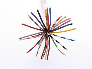
An audio multicore cable is a thick cable which usually contains 4–64 individual audio cables inside a common, sturdy outer jacket. Audio multicore cables are used to convey many audio signals between two locations, such as in audio recording, sound reinforcement, PA systems and broadcasting. Multicores often route many signals from microphones or musical instruments to a mixing console, and can also carry signals from a mixing console back to speakers.

In an electrical system, a ground loop or earth loop occurs when two points of a circuit are intended to have the same ground reference potential but instead have a different potential between them. This is typically caused when enough current is flowing in the connection between the two ground points to produce a voltage drop and cause two points to be at different potentials. Current may be produced in a circular ground connection by electromagnetic induction.

<span class="mw-page-title-main">Pickup (music technology)</span> Transducer that senses vibration of musical instruments

A pickup is a transducer that captures or senses mechanical vibrations produced by musical instruments, particularly stringed instruments such as the electric guitar, and converts these to an electrical signal that is amplified using an instrument amplifier to produce musical sounds through a loudspeaker in a speaker enclosure. The signal from a pickup can also be recorded directly.

<span class="mw-page-title-main">Differential signalling</span> Method for electrically transmitting information

Differential signalling is a method for electrically transmitting information using two complementary signals. The technique sends the same electrical signal as a differential pair of signals, each in its own conductor. The pair of conductors can be wires in a twisted-pair or ribbon cable or traces on a printed circuit board.

<span class="mw-page-title-main">Unbalanced line</span>

In telecommunications and electrical engineering in general, an unbalanced line is a pair of conductors intended to carry electrical signals, which have unequal impedances along their lengths and to ground and other circuits. Examples of unbalanced lines are coaxial cable or the historic earth return system invented for the telegraph, but rarely used today. Unbalanced lines are to be contrasted with balanced lines, such as twin-lead or twisted pair which use two identical conductors to maintain impedance balance throughout the line. Balanced and unbalanced lines can be interfaced using a device called a balun.

In electronics, crosstalk is any phenomenon by which a signal transmitted on one circuit or channel of a transmission system creates an undesired effect in another circuit or channel. Crosstalk is usually caused by undesired capacitive, inductive, or conductive coupling from one circuit or channel to another.

Transposition is the periodic swapping of positions of the conductors of a transmission line, in order to reduce crosstalk and otherwise improve transmission. In telecommunications this applies to balanced pairs whilst in power transmission lines three conductors are periodically transposed.

<span class="mw-page-title-main">Choke (electronics)</span> Inductor used as a low-pass filter

In electronics, a choke is an inductor used to block higher-frequency alternating currents (AC) while passing direct current (DC) and lower-frequency ACs in a circuit. A choke usually consists of a coil of insulated wire often wound on a magnetic core, although some consist of a doughnut-shaped ferrite bead strung on a wire. The choke's impedance increases with frequency. Its low electrical resistance passes both AC and DC with little power loss, but its reactance limits the amount of AC passed.

<span class="mw-page-title-main">Test probe</span>

A test probe is a physical device used to connect electronic test equipment to a device under test (DUT). Test probes range from very simple, robust devices to complex probes that are sophisticated, expensive, and fragile. Specific types include test prods, oscilloscope probes and current probes. A test probe is often supplied as a test lead, which includes the probe, cable and terminating connector.

<span class="mw-page-title-main">Transformer types</span> Overview of electrical transformer types

A variety of types of electrical transformer are made for different purposes. Despite their design differences, the various types employ the same basic principle as discovered in 1831 by Michael Faraday, and share several key functional parts.

In electrical engineering, a balanced circuit is electronic circuitry for use with a balanced line, or the balanced line itself. Balanced lines are a common method of transmitting many types of electrical signals between two points on two wires. In a balanced line, the two signal lines are of a matched impedance to help ensure that interference, induced in the line, is common-mode and can be removed at the receiving end by circuitry with good common-mode rejection. To maintain the balance, circuit blocks which interface to the line or are connected in the line must also be balanced.

In electrical engineering, a common-mode signal is the identical component of voltage present at both input terminals of an electrical device. In telecommunication, the common-mode signal on a transmission line is also known as longitudinal voltage.

Nominal impedance in electrical engineering and audio engineering refers to the approximate designed impedance of an electrical circuit or device. The term is applied in a number of different fields, most often being encountered in respect of:

References

  1. GB 1407,Oliver Heaviside,"Electrical Conductors, &c.",published 1880-04-06
  2. The Importance of Star-Quad Microphone Cable
  3. Evaluating Microphone Cable Performance & Specifications
  4. The Star Quad Story
  5. What's Special About Star-Quad Cable?
  6. How Starquad Works
  7. "SynAudCon EMI Project".
  8. Lampen, Stephen H. (2002). Audio/Video Cable Installer's Pocket Guide. McGraw-Hill. pp. 32, 110, 112. ISBN   0071386211.
  9. Rayburn, Ray (2011). Eargle's The Microphone Book: From Mono to Stereo to Surround – A Guide to Microphone Design and Application (3 ed.). Focal Press. pp. 164–166. ISBN   0240820754.
  10. "L-4E6AT star-quad cable specifications". canare.com. Canare.
  11. Canare 4S11 Star Quad Speaker Cable Specifications