Steam diesel hybrid locomotive

Last updated

A steam diesel hybrid locomotive is a railway locomotive with a piston engine which could run on either steam from a boiler or diesel fuel. Examples were built in the United Kingdom, Soviet Union and Italy but the relatively high cost of fuel oil, or failure to resolve problems caused by technical complexity, meant that the designs were not pursued.

Contents

Kitson-Still system

In 1926 Kitson and Company, Leeds, built an experimental example for the London and North Eastern Railway, using as their model the Still engine already in use for stationary and marine applications. It was on trial until 1934, but then scrapped. It was designed because a steam engine offered a high starting torque—a tractive force of 25,450  lbf (113.2  kN ) was available—while a diesel engine offered a high fuel efficiency and it was considered desirable to combine both benefits in one machine. [1]

Construction

In outline the machine resembled a conventional 2-6-2T steam locomotive, but it had four pairs of horizontally opposed cylinders (13.5 in (340 mm) bore × 15.5 in (390 mm) stroke) mounted longitudinally above the frame and driving a crankshaft placed between them, with the further drivetrain powered by gears. [2] The cylinders were made double-ended, with the rod end of each cylinder for steam and the closed end fitted with a diesel injector. (Some drawings, published in contemporary magazines, show only two pairs of cylinders and it seems that this was one of the design features that was changed during development.) The boiler, with a diameter of only 51 in (130 cm) and a small internal firebox, was mounted above. The "regenerator", capturing heat from the exhaust, was integral with the boiler and had 38 tubes totalling a heating area of 508 sq ft (47.2 m2). The driving position was in the usual place behind the boiler, and tanks—400 imp gal (1,800 L) for fuel and 1,000 imp gal (4,500 L) for water—were mounted on the frame at the rear, one above the other. [1]

Operation

The sequence of operation began with heating the boiler in the normal way, but using fuel oil instead of coal. The start from rest was made with steam power, but at about 5 mph (8.0 km/h) the diesel injectors were started and the steam turned off. The waste heat from the cylinder jackets and diesel exhaust then maintained the boiler in steam for auxiliary functions (brakes and whistle) and in readiness to supplement the diesel power if required, or for the next start. The temperature of the water jacket, maintained at considerably above boiling point, assisted the compression ignition of the diesel fuel and only a relatively low compression ratio was required. [3] Because steam power provided the torque required for starting, no form of variable transmission was necessary and a permanent reduction geartrain of ratio 1·878 to 1 was fitted. [1]

Overall power output (800 bhp under diesel, 1,000 bhp when supplemented with steam) [2] did not compare well with conventional steam locomotives, although the performance on gradients was good because of the gearing. During the trials it was used successfully with coal trains and it proved very efficient in terms of fuel used, because the waste heat from the diesel power was recovered. However its running costs depended on the price differential between coal and oil and this was not favourable. When Kitson & Co. failed in 1934 the LNER handed the machine back to the company's receivers and it was dismantled.

Cristiani compressed steam system

The Italian Cristiani Compressed Steam System used the process of mechanical vapour recompression. A diesel engine compressed steam which was then fed to conventional steam engine cylinders. The exhaust steam was re-compressed and used again. There must have been a small boiler to generate the initial charge of steam but this is not shown in the diagram. [4]

The steam was used mainly as a transmission system but the locomotive does count as a hybrid because some steam storage was provided. A possible advantage of the system was that it enabled existing steam locomotives to be converted to diesel operation but this did not come to fruition.

Patents for the system were held by Severino Cristiani and Secondo Sacerdole in Italy and it was promoted in England by Captain William Peter Durtnall. [5] A trial was made in England, using two "Paragon" marine petrol engines, under the name "Paragon-Cristiani". The equipment was mounted on a 0-6-0 chassis (works number 3513/1923) built by Hawthorn Leslie and Company. It was not a success and the chassis was converted to a conventional 0-6-0ST named "Stagshaw" which is preserved on the Tanfield Railway. [6]

Other trials

Soviet Locomotive TP1Stalinets Teploparovoz TP1.jpg
Soviet Locomotive TP1Stalinets

Soviet Union

The Soviet Union built three large experimental locomotives between 1939 and 1946. [7]

The first prototype, numbered 8000, a 2-8-2 from the Vorishilovgrad works, had two pairs of outside double-acting opposing pistons; when diesel power was initiated, at about 20 km/h (12 mph), diesel fuel was injected into the centre portion between the pistons which thus became the compression-ignition chamber, while the outer ends of the cylinders continued to receive steam in the normal way. Although the unit remained in passenger service, intermittently, until 1946, when it was tested again. It was put into storage in 1948. It was not considered a success as its 25-tonne axle load was too high, it rode hard on the tracks and was prone to cracking cylinders. [8]

TP1-1, the second prototype (illustrated right), under the name of Сталинец (Stalinets), was a cab-forward condensing 2-10-2 from the Kolomna works, used gas produced from an anthracite coal plant in the tender to fuel its spark-ignition internal combustion cylinders, along with anthracite pulverised in the gasification plant to heat the boiler. There were a total of eight pistons in four cylinders in an opposed-piston configuration; two steam cylinders and two coal gas cylinders. It was reported to have only functioned properly at speeds of 25–30 km/h and below as travelling faster for about 10–15 minutes would cause the gas mixture to combust prematurely when entering the combustion chamber. Issues were reportedly sorted out by 1941 but the project was abandoned during Operation Barbarossa and the outbreak of WW2 on Soviet territory. [7] [8]

Number 8001, the third experiment, also named Сталинец, was a unit developed from the previous Voroshilovgrad design in 1946. It was also a 2-10-2 configuration and had the centre space in the cylinders, between the opposed pistons, intended to combine compression ignition and steam expansive working in the same chamber. It was reportedly almost a complete disaster and placed in storage in 1948. [7] [8]

Switzerland

In 1925, Jakob Buchli of Switzerland obtained US patent 1559548 for a combined steam and internal-combustion engined locomotive. This differed from the Kitson-Still system in that there was no waste heat recovery and the steam and internal combustion engines had separate cylinders (vertically mounted in the tender), but both driving the same traction wheels. Buchli specified that "…the steam generator is supported upon one vehicle…and the steam and internal combustion engine cylinders together with their driving gear are carried by a separate truck or vehicle". His proposal was for the "steam generator vehicle" to be in the form of a traditional steam locomotive boiler with driver's cab, but without pistons. A "flexible pipe" would lead steam to the pistons within the "detachably coupled…truck" (tender). His claimed advantages were the reduced complexity of a combined transmission system, the improved comfort of the operators being separated from the driving cylinders and the differing maintenance requirements of steam and diesel (such as boiler washouts) being more easily accommodated when the units were detachable. [9] It is not known whether any locomotives to Buchli's design were actually built.

United States

In 1954 Chicago inventor Charles Denker patented a system whereby the exhaust from a conventional four-stroke diesel engine was directed into a large-diameter steam cylinder. There was no boiler: instead a pump, operated by a cam driven from the common crankshaft, injected water (warmed by the diesel cylinder water jacket) into the steam cylinder so that it was instantly evaporated by the hot exhaust gases, powering the piston by expansion. Again, no operational examples are known. [10]

Related Research Articles

<span class="mw-page-title-main">Diesel engine</span> Type of internal combustion engine

The diesel engine, named after Rudolf Diesel, is an internal combustion engine in which ignition of the fuel is caused by the elevated temperature of the air in the cylinder due to mechanical compression; thus, the diesel engine is called a compression-ignition engine. This contrasts with engines using spark plug-ignition of the air-fuel mixture, such as a petrol engine or a gas engine.

<span class="mw-page-title-main">Reciprocating engine</span> Engine utilising one or more reciprocating pistons

A reciprocating engine, also often known as a piston engine, is typically a heat engine that uses one or more reciprocating pistons to convert high temperature and high pressure into a rotating motion. This article describes the common features of all types. The main types are: the internal combustion engine, used extensively in motor vehicles; the steam engine, the mainstay of the Industrial Revolution; and the Stirling engine for niche applications. Internal combustion engines are further classified in two ways: either a spark-ignition (SI) engine, where the spark plug initiates the combustion; or a compression-ignition (CI) engine, where the air within the cylinder is compressed, thus heating it, so that the heated air ignites fuel that is injected then or earlier.

<span class="mw-page-title-main">Miller cycle</span> Thermodynamic cycle

In engineering, the Miller cycle is a thermodynamic cycle used in a type of internal combustion engine. The Miller cycle was patented by Ralph Miller, an American engineer, U.S. patent 2,817,322 dated Dec 24, 1957. The engine may be two- or four-stroke and may be run on diesel fuel, gases, or dual fuel. It uses a supercharger or a turbocharger to offset the performance loss of the Atkinson cycle.

A stratified charge engine describes a certain type of internal combustion engine, usually spark ignition (SI) engine that can be used in trucks, automobiles, portable and stationary equipment. The term "stratified charge" refers to the working fluids and fuel vapors entering the cylinder. Usually the fuel is injected into the cylinder or enters as a fuel rich vapor where a spark or other means are used to initiate ignition where the fuel rich zone interacts with the air to promote complete combustion. A stratified charge can allow for slightly higher compression ratios without "knock," and leaner air/fuel ratio than in conventional internal combustion engines.

<span class="mw-page-title-main">Four-stroke engine</span> Internal combustion engine type

A four-strokeengine is an internal combustion (IC) engine in which the piston completes four separate strokes while turning the crankshaft. A stroke refers to the full travel of the piston along the cylinder, in either direction. The four separate strokes are termed:

  1. Intake: Also known as induction or suction. This stroke of the piston begins at top dead center (T.D.C.) and ends at bottom dead center (B.D.C.). In this stroke the intake valve must be in the open position while the piston pulls an air-fuel mixture into the cylinder by producing a partial vacuum in the cylinder through its downward motion.
  2. Compression: This stroke begins at B.D.C, or just at the end of the suction stroke, and ends at T.D.C. In this stroke the piston compresses the air-fuel mixture in preparation for ignition during the power stroke (below). Both the intake and exhaust valves are closed during this stage.
  3. Combustion: Also known as power or ignition. This is the start of the second revolution of the four stroke cycle. At this point the crankshaft has completed a full 360 degree revolution. While the piston is at T.D.C. the compressed air-fuel mixture is ignited by a spark plug or by heat generated by high compression, forcefully returning the piston to B.D.C. This stroke produces mechanical work from the engine to turn the crankshaft.
  4. Exhaust: Also known as outlet. During the exhaust stroke, the piston, once again, returns from B.D.C. to T.D.C. while the exhaust valve is open. This action expels the spent air-fuel mixture through the exhaust port.
<span class="mw-page-title-main">Brayton cycle</span> Thermodynamic cycle

The Brayton cycle, also known as the Joule cycle, is a thermodynamic cycle that describes the operation of certain heat engines that have air or some other gas as their working fluid. It is characterized by isentropic compression and expansion, and isobaric heat addition and rejection, though practical engines have adiabatic rather than isentropic steps.

A combustion chamber is part of an internal combustion engine in which the fuel/air mix is burned. For steam engines, the term has also been used for an extension of the firebox which is used to allow a more complete combustion process.

William Hall Barnett is described as a 'founder' in his 1836 patent, and an 'ironfounder' in his 1838 patent, and later as an engineer and gas engineer, working in Brighton, UK. He worked for many years for the Brighton and Hove General Gas Company. He was born in Bradford and died in Brighton.

Homogeneous Charge Compression Ignition (HCCI) is a form of internal combustion in which well-mixed fuel and oxidizer are compressed to the point of auto-ignition. As in other forms of combustion, this exothermic reaction produces heat that can be transformed into work in a heat engine.

In the context of an internal combustion engine, the term stroke has the following related meanings:

<span class="mw-page-title-main">Bourke engine</span> Type of internal combustion engine

The Bourke engine was an attempt by Russell Bourke, in the 1920s, to improve the two-stroke internal combustion engine. Despite finishing his design and building several working engines, the onset of World War II, lack of test results, and the poor health of his wife compounded to prevent his engine from ever coming successfully to market. The main claimed virtues of the design are that it has only two moving parts, is lightweight, has two power pulses per revolution, and does not need oil mixed into the fuel.

<span class="mw-page-title-main">Hot-bulb engine</span> Internal combustion engine

The hot-bulb engine, also known as a semi-diesel, is a type of internal combustion engine in which fuel ignites by coming in contact with a red-hot metal surface inside a bulb, followed by the introduction of air (oxygen) compressed into the hot-bulb chamber by the rising piston. There is some ignition when the fuel is introduced, but it quickly uses up the available oxygen in the bulb. Vigorous ignition takes place only when sufficient oxygen is supplied to the hot-bulb chamber on the compression stroke of the engine.

Engine efficiency of thermal engines is the relationship between the total energy contained in the fuel, and the amount of energy used to perform useful work. There are two classifications of thermal engines-

  1. Internal combustion and
  2. External combustion engines.

The term six-stroke engine has been applied to a number of alternative internal combustion engine designs that attempt to improve on traditional two-stroke and four-stroke engines. Claimed advantages may include increased fuel efficiency, reduced mechanical complexity, and/or reduced emissions. These engines can be divided into two groups based on the number of pistons that contribute to the six strokes.

<span class="mw-page-title-main">Hornsby-Akroyd oil engine</span> Early internal combustion engine design using heavy oil.

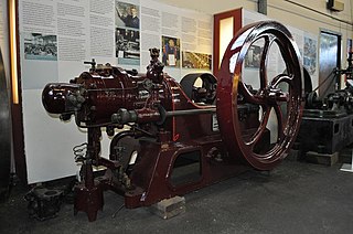
The Hornsby-Akroyd oil engine, named after its inventor Herbert Akroyd Stuart and the manufacturer Richard Hornsby & Sons, was the first successful design of an internal combustion engine using heavy oil as a fuel. It was the first to use a separate vapourising combustion chamber and is the forerunner of all hot-bulb engines, which are considered predecessors of the similar Diesel engine, developed a few years later.

<span class="mw-page-title-main">Free-piston engine</span>

A free-piston engine is a linear, 'crankless' internal combustion engine, in which the piston motion is not controlled by a crankshaft but determined by the interaction of forces from the combustion chamber gases, a rebound device and a load device.

<span class="mw-page-title-main">Two-stroke diesel engine</span> Engine type

A two-stroke diesel engine is a diesel engine that uses compression ignition in a two-stroke combustion cycle. It was invented by Hugo Güldner in 1899.

The Still engine was a piston engine that simultaneously used both steam power from an external boiler, and internal combustion from gasoline or diesel, in the same unit. The waste heat from the cylinder and internal combustion exhaust was directed to the steam boiler, resulting in claimed fuel savings of up to 10%.

Internal combustion engines come in a wide variety of types, but have certain family resemblances, and thus share many common types of components.

<span class="mw-page-title-main">Internal combustion engine</span> Engine in which the combustion of a fuel occurs with an oxidizer in a combustion chamber

An internal combustion engine is a heat engine in which the combustion of a fuel occurs with an oxidizer in a combustion chamber that is an integral part of the working fluid flow circuit. In an internal combustion engine, the expansion of the high-temperature and high-pressure gases produced by combustion applies direct force to some component of the engine. The force is typically applied to pistons, turbine blades, a rotor, or a nozzle. This force moves the component over a distance, transforming chemical energy into kinetic energy which is used to propel, move or power whatever the engine is attached to.

References

  1. 1 2 3 Franco, Isaac; Labryn, P (1931). Internal-Combustion Locomotives and Motor Coaches. Leiden: Nijhoff. pp. 88–89. ISBN   9789401757652.
  2. 1 2 "Kitson-Still locomotives". Railway Age . Vol. 85, no. 14. 6 October 1928. pp. 669–70.
  3. Franco; Labryn (1931) p49
  4. "The Cristiani Compressed Steam System".
  5. "Internal combustion locomotive engineers". Durtnall, William Peter.
  6. "BackTrack Volume 23 (2009)".
  7. 1 2 3 "Russian Reforms- Unusual Russian Locomotive Technology". www.douglas-self.com. Retrieved 3 June 2018.
  8. 1 2 3 Westwood, J.N. (1982). Soviet locomotive technology during industrialization. London: Palgrave Macmillan. pp. 156–159. ISBN   9780333275160.
  9. "Combined steam and internal-combustion engine locomotive". European Patent Office . Retrieved 18 December 2017.
  10. Denker, Charles T (17 June 1954). "US patent 2,791,881 Combined Diesel and Steam Engine". USPTO . Retrieved 4 January 2018.

Notes

See also