Successive-approximation ADC

Last updated
Successive-approximation ADC block diagram showing digital-to-analog converter (DAC), end of conversion indicator (EOC), successive approximation register (SAR), sample and hold circuit (S/H), input voltage (Vin) and reference voltage (Vref) SA ADC block diagram.png
Successive-approximation ADC block diagram showing digital-to-analog converter (DAC), end of conversion indicator (EOC), successive approximation register (SAR), sample and hold circuit (S/H), input voltage (Vin) and reference voltage (Vref)

A successive-approximation ADC is a type of analog-to-digital converter that converts a continuous analog waveform into a discrete digital representation using a binary search through all possible quantization levels before finally converging upon a digital output for each conversion.

Contents

Algorithm

The successive-approximation analog-to-digital converter circuit typically consists of four chief subcircuits:

  1. A sample-and-hold circuit to acquire the input voltage Vin.
  2. An analog voltage comparator that compares Vin to the output of the internal DAC and outputs the result of the comparison to the successive-approximation register (SAR).
  3. A successive-approximation register subcircuit designed to supply an approximate digital code of Vin to the internal DAC.
  4. An internal reference DAC that, for comparison with Vref, supplies the comparator with an analog voltage equal to the digital code output of the SARin.
Animation of a 4-bit successive-approximation ADC 4-bit Successive Approximation DAC.gif
Animation of a 4-bit successive-approximation ADC

The successive approximation register is initialized so that the most significant bit (MSB) is equal to a digital 1. This code is fed into the DAC, which then supplies the analog equivalent of this digital code (Vref/2) into the comparator circuit for comparison with the sampled input voltage. If this analog voltage exceeds Vin, then the comparator causes the SAR to reset this bit; otherwise, the bit is left as 1. Then the next bit is set to 1 and the same test is done, continuing this binary search until every bit in the SAR has been tested. The resulting code is the digital approximation of the sampled input voltage and is finally output by the SAR at the end of the conversion (EOC).

Mathematically, let Vin = xVref, so x in [−1, 1] is the normalized input voltage. The objective is to approximately digitize x to an accuracy of 12n. The algorithm proceeds as follows:

  1. Initial approximation x0 = 0.
  2. ith approximation xi = xi−1s(xi−1x)/2i, where, s(x) is the signum function (sgn(x) = +1 for x ≥ 0, −1 for x < 0). It follows using mathematical induction that |xnx| ≤ 1/2n.

As shown in the above algorithm, a SAR ADC requires:

  1. An input voltage source Vin.
  2. A reference voltage source Vref to normalize the input.
  3. A DAC to convert the ith approximation xi to a voltage.
  4. A comparator to perform the function s(xix) by comparing the DAC's voltage with the input voltage.
  5. A register to store the output of the comparator and apply xi−1s(xi−1x)/2i.
Operation of successive-approximation ADC as input voltage falls from 5 to 0 V. Iterations on the x axis. Approximation value on the y axis. ADC animation 20.gif
Operation of successive-approximation ADC as input voltage falls from 5 to 0 V. Iterations on the x axis. Approximation value on the y axis.

Example 1: The ten steps to converting an analog input to 10 bit digital, using successive approximation, are shown here for all voltages from 5 V to 0 V in 0.1 V iterations. Since the reference voltage is 5 V, when the input voltage is also 5 V, all bits are set. As the voltage is decreased to 4.9 V, only some of the least significant bits are cleared. The MSB will remain set until the input is one half the reference voltage, 2.5 V.

The binary weights assigned to each bit, starting with the MSB, are 2.5, 1.25, 0.625, 0.3125, 0.15625, 0.078125, 0.0390625, 0.01953125, 0.009765625, 0.0048828125. All of these add up to 4.9951171875, meaning binary 1111111111, or one LSB less than 5.

When the analog input is being compared to the internal DAC output, it effectively is being compared to each of these binary weights, starting with the 2.5 V and either keeping it or clearing it as a result. Then by adding the next weight to the previous result, comparing again, and repeating until all the bits and their weights have been compared to the input, the end result, a binary number representing the analog input, is found.


Example 2: The working of a 4-bit successive approximation ADC is illustrated below. The MSB is initially set to 1 whereas the remaining digits are set to zero. If the input voltage is lower than the value stored in the register, on the next clock cycle, the register changes its value to that illustrated in the figure by following the green line. If the input voltage is higher, then on the next clock cycle, the register changes its value to that illustrated in the figure by following the red line. The simplified structure of this type of ADC that acts on 2n volts range can be expressed as an algorithm:
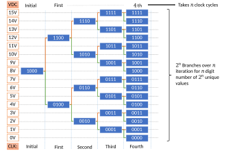
  1. Initialize register with MSB set to 1 and all other values set to zero.
  2. In n-th clock cycle, if voltage is higher than digital equivalent voltage of the number in register, the (n+1)-th digit from the left is set to 1. If the voltage were lower than digital equivalent voltage, then n-th digit from left is set to zero and the next digit is set to 1. To perform a conversion, an N-bit ADC requires N such clock cycles excluding the initial state.
Working of successive approximation ADC
Successive-approximation ADC example Setup.svg
Setup where output values of the ADC are arranged in a grid, vertical axis corresponding to voltage. It is a 4-bit ADC that measures input voltages from 0V to 15V.
Successive-approximation ADC example working value 1.svg
Previously established setup where an input voltage of 10.4V is provided.
Successive-approximation ADC example working value 2.svg
Previously established setup where an input voltage of 9.4V is provided.

The successive approximation ADC can be alternatively explained by first uniformly assigning each digital output to corresponding ranges as shown. It can be seen that the algorithm essentially divides the voltage range into two regions and checks which of the two regions the input voltage belongs to. Successive steps involve taking the identified region from before and further dividing the region into two and continuing identification. This occurs until all possible choices of digital representations are exhausted, leaving behind an identified region that corresponds to only one of the digital representations.

Variants

Charge-redistribution successive-approximation ADC

Charge-scaling DAC ChargeScalingDAC.png
Charge-scaling DAC

One of the most common implementations of the successive-approximation ADC, the charge-redistribution successive-approximation ADC, uses a charge-scaling DAC. The charge-scaling DAC simply consists of an array of individually switched binary-weighted capacitors. The amount of charge upon each capacitor in the array is used to perform the aforementioned binary search in conjunction with a comparator internal to the DAC and the successive-approximation register.

3 bits simulation of a capacitive ADC CAPadc.png
3 bits simulation of a capacitive ADC
  1. The capacitor array is completely discharged to the offset voltage of the comparator, VOS. This step provides automatic offset cancellation (i.e. the offset voltage represents nothing but dead charge, which can't be juggled by the capacitors).
  2. All of the capacitors within the array are switched to the input signal Vin. The capacitors now have a charge equal to their respective capacitance times the input voltage minus the offset voltage upon each of them.
  3. The capacitors are then switched so that this charge is applied across the comparator input, creating a comparator input voltage equal to Vin.
  4. The actual conversion process proceeds. First, the MSB capacitor is switched to Vref, which corresponds to the full-scale range of the ADC. Due to the binary-weighting of the array, the MSB capacitor forms a 1:1 charge divider with the rest of the array. Thus, the input voltage to the comparator is now Vin + Vref2. Subsequently, if Vin is greater than Vref2, then the comparator outputs a digital 1 as the MSB, otherwise it outputs a digital 0 as the MSB. Each capacitor is tested in the same manner until the comparator input voltage converges to the offset voltage, or at least as close as possible given the resolution of the DAC.

Use with non-ideal analog circuits

When implemented as an analog circuit – where the value of each successive bit is not perfectly 2N (e.g. 1.1, 2.12, 4.05, 8.01, etc.) – a successive-approximation approach might not output the ideal value because the binary search algorithm incorrectly removes what it believes to be half of the values the unknown input cannot be. Depending on the difference between actual and ideal performance, the maximal error can easily exceed several LSBs, especially as the error between the actual and ideal 2N becomes large for one or more bits. Since the actual input is unknown, it is therefore very important that accuracy of the analog circuit used to implement a SAR ADC be very close to the ideal 2N values; otherwise, it cannot guarantee a best match search.

See also

Related Research Articles

<span class="mw-page-title-main">Analog-to-digital converter</span> System that converts an analog signal into a digital signal

In electronics, an analog-to-digital converter is a system that converts an analog signal, such as a sound picked up by a microphone or light entering a digital camera, into a digital signal. An ADC may also provide an isolated measurement such as an electronic device that converts an analog input voltage or current to a digital number representing the magnitude of the voltage or current. Typically the digital output is a two's complement binary number that is proportional to the input, but there are other possibilities.

<span class="mw-page-title-main">Companding</span> Method of mitigating the detrimental effects of a channel with limited dynamic range

In telecommunication and signal processing, companding is a method of mitigating the detrimental effects of a channel with limited dynamic range. The name is a portmanteau of the words compressing and expanding, which are the functions of a compander at the transmitting and receiving ends, respectively. The use of companding allows signals with a large dynamic range to be transmitted over facilities that have a smaller dynamic range capability. Companding is employed in telephony and other audio applications such as professional wireless microphones and analog recording.

<span class="mw-page-title-main">Comparator</span> Device that compares two voltages or currents

In electronics, a comparator is a device that compares two voltages or currents and outputs a digital signal indicating which is larger. It has two analog input terminals and and one binary digital output . The output is ideally

<span class="mw-page-title-main">Delta modulation</span>

A delta modulation is an analog-to-digital and digital-to-analog signal conversion technique used for transmission of voice information where quality is not of primary importance. DM is the simplest form of differential pulse-code modulation (DPCM) where the difference between successive samples is encoded into n-bit data streams. In delta modulation, the transmitted data are reduced to a 1-bit data stream representing either up (↗) or down (↘). Its main features are:

<span class="mw-page-title-main">Digital-to-analog converter</span> Device that converts a digital signal into an analog signal

In electronics, a digital-to-analog converter is a system that converts a digital signal into an analog signal. An analog-to-digital converter (ADC) performs the reverse function.

<span class="mw-page-title-main">Sampling (signal processing)</span> Measurement of a signal at discrete time intervals

In signal processing, sampling is the reduction of a continuous-time signal to a discrete-time signal. A common example is the conversion of a sound wave to a sequence of "samples". A sample is a value of the signal at a point in time and/or space; this definition differs from the term's usage in statistics, which refers to a set of such values.

<span class="mw-page-title-main">TI MSP430</span>

The MSP430 is a mixed-signal microcontroller family from Texas Instruments, first introduced on 14 February 1992. Built around a 16-bit CPU, the MSP430 was designed for use with low power consumption embedded applications and for low cost.

A numerically controlled oscillator (NCO) is a digital signal generator which creates a synchronous, discrete-time, discrete-valued representation of a waveform, usually sinusoidal. NCOs are often used in conjunction with a digital-to-analog converter (DAC) at the output to create a direct digital synthesizer (DDS).

In digital electronics, a binary decoder is a combinational logic circuit that converts binary information from the n coded inputs to a maximum of 2n unique outputs. They are used in a wide variety of applications, including instruction decoding, data multiplexing and data demultiplexing, seven segment displays, and as address decoders for memory and port-mapped I/O.

<span class="mw-page-title-main">Sample and hold</span>

In electronics, a sample and hold circuit is an analog device that samples the voltage of a continuously varying analog signal and holds its value at a constant level for a specified minimum period of time. Sample and hold circuits and related peak detectors are the elementary analog memory devices. They are typically used in analog-to-digital converters to eliminate variations in input signal that can corrupt the conversion process. They are also used in electronic music, for instance to impart a random quality to successively-played notes.

In signal processing, oversampling is the process of sampling a signal at a sampling frequency significantly higher than the Nyquist rate. Theoretically, a bandwidth-limited signal can be perfectly reconstructed if sampled at the Nyquist rate or above it. The Nyquist rate is defined as twice the bandwidth of the signal. Oversampling is capable of improving resolution and signal-to-noise ratio, and can be helpful in avoiding aliasing and phase distortion by relaxing anti-aliasing filter performance requirements.

<span class="mw-page-title-main">Delta-sigma modulation</span> Method for converting signals between digital and analog

Delta-sigma modulation is an oversampling method for encoding signals into low bit depth digital signals at a very high sample-frequency as part of the process of delta-sigma analog-to-digital converters (ADCs) and digital-to-analog converters (DACs). Delta-sigma modulation achieves high quality by utilizing a negative feedback loop during quantization to the lower bit depth that continuously corrects quantization errors and moves quantization noise to higher frequencies well above the original signal's bandwidth. Subsequent low-pass filtering for demodulation easily removes this high frequency noise and time averages to achieve high accuracy in amplitude.

A resistor ladder is an electrical circuit made from repeating units of resistors, in specific configurations.

A flash ADC is a type of analog-to-digital converter that uses a linear voltage ladder with a comparator at each "rung" of the ladder to compare the input voltage to successive reference voltages. Often these reference ladders are constructed of many resistors; however, modern implementations show that capacitive voltage division is also possible. The output of these comparators is generally fed into a digital encoder, which converts the inputs into a binary value.

Verilog-AMS is a derivative of the Verilog hardware description language that includes Analog and Mixed-Signal extensions (AMS) in order to define the behavior of analog and mixed-signal systems. It extends the event-based simulator loops of Verilog/SystemVerilog/VHDL, by a continuous-time simulator, which solves the differential equations in analog-domain. Both domains are coupled: analog events can trigger digital actions and vice versa.

<span class="mw-page-title-main">Audio bit depth</span> Number of bits of information recorded for each digital audio sample

In digital audio using pulse-code modulation (PCM), bit depth is the number of bits of information in each sample, and it directly corresponds to the resolution of each sample. Examples of bit depth include Compact Disc Digital Audio, which uses 16 bits per sample, and DVD-Audio and Blu-ray Disc which can support up to 24 bits per sample.

<span class="mw-page-title-main">Differential nonlinearity</span>

Differential nonlinearity is a commonly used measure of performance in digital-to-analog (DAC) and analog-to-digital (ADC) converters. It is a term describing the deviation between two analog values corresponding to adjacent input digital values. It is an important specification for measuring error in a digital-to-analog converter (DAC); the accuracy of a DAC is mainly determined by this specification. Ideally, any two adjacent digital codes correspond to output analog voltages that are exactly one Least Significant Bit (LSB) apart. Differential non-linearity is a measure of the worst-case deviation from the ideal 1 LSB step. For example, a DAC with a 1.5 LSB output change for a 1 LSB digital code change exhibits 1⁄2 LSB differential non-linearity. Differential non-linearity may be expressed in fractional bits or as a percentage of full scale. A differential non-linearity greater than 1 LSB may lead to a non-monotonic transfer function in a DAC. It is also known as a missing code.

Integral nonlinearity is a commonly used measure of performance in digital-to-analog (DAC) and analog-to-digital (ADC) converters. In DACs, it is a measure of the deviation between the ideal output value and the actual measured output value for a certain input code. In ADCs, it is the deviation between the ideal input threshold value and the measured threshold level of a certain output code. This measurement is performed after offset and gain errors have been compensated.

An integrating ADC is a type of analog-to-digital converter that converts an unknown input voltage into a digital representation through the use of an integrator. In its basic implementation, the dual-slope converter, the unknown input voltage is applied to the input of the integrator and allowed to ramp for a fixed time period. Then a known reference voltage of opposite polarity is applied to the integrator and is allowed to ramp until the integrator output returns to zero. The input voltage is computed as a function of the reference voltage, the constant run-up time period, and the measured run-down time period. The run-down time measurement is usually made in units of the converter's clock, so longer integration times allow for higher resolutions. Likewise, the speed of the converter can be improved by sacrificing resolution.

The following outline is provided as an overview of and topical guide to electronics:

References

    Further reading