Related Research Articles
In information theory, data compression, source coding, or bit-rate reduction is the process of encoding information using fewer bits than the original representation. Any particular compression is either lossy or lossless. Lossless compression reduces bits by identifying and eliminating statistical redundancy. No information is lost in lossless compression. Lossy compression reduces bits by removing unnecessary or less important information. Typically, a device that performs data compression is referred to as an encoder, and one that performs the reversal of the process (decompression) as a decoder.
Lossless compression is a class of data compression that allows the original data to be perfectly reconstructed from the compressed data with no loss of information. Lossless compression is possible because most real-world data exhibits statistical redundancy. By contrast, lossy compression permits reconstruction only of an approximation of the original data, though usually with greatly improved compression rates.
Software testing is the act of examining the artifacts and the behavior of the software under test by validation and verification. Software testing can also provide an objective, independent view of the software to allow the business to appreciate and understand the risks of software implementation. Test techniques include, but not necessarily limited to:

Digital electronics is a field of electronics involving the study of digital signals and the engineering of devices that use or produce them. This is in contrast to analog electronics and analog signals.

The VHSIC Hardware Description Language (VHDL) is a hardware description language (HDL) that can model the behavior and structure of digital systems at multiple levels of abstraction, ranging from the system level down to that of logic gates, for design entry, documentation, and verification purposes. Since 1987, VHDL has been standardized by the Institute of Electrical and Electronics Engineers (IEEE) as IEEE Std 1076; the latest version of which is IEEE Std 1076-2019. To model analog and mixed-signal systems, an IEEE-standardized HDL based on VHDL called VHDL-AMS has been developed.

Magic is an electronic design automation (EDA) layout tool for very-large-scale integration (VLSI) integrated circuit (IC) originally written by John Ousterhout and his graduate students at UC Berkeley. Work began on the project in February 1983. A primitive version was operational by April 1983, when Joan Pendleton, Shing Kong and other graduate student chip designers suffered through many fast revisions devised to meet their needs in designing the SOAR CPU chip, a follow-on to Berkeley RISC.
ATPG is an electronic design automation method/technology used to find an input sequence that, when applied to a digital circuit, enables automatic test equipment to distinguish between the correct circuit behavior and the faulty circuit behavior caused by defects. The generated patterns are used to test semiconductor devices after manufacture, or to assist with determining the cause of failure. The effectiveness of ATPG is measured by the number of modeled defects, or fault models, detectable and by the number of generated patterns. These metrics generally indicate test quality and test application time. ATPG efficiency is another important consideration that is influenced by the fault model under consideration, the type of circuit under test, the level of abstraction used to represent the circuit under test, and the required test quality.
JTAG is an industry standard for verifying designs and testing printed circuit boards after manufacture.
A fault model is an engineering model of something that could go wrong in the construction or operation of a piece of equipment. From the model, the designer or user can then predict the consequences of this particular fault. Fault models can be used in almost all branches of engineering.

Boundary scan is a method for testing interconnects on printed circuit boards or sub-blocks inside an integrated circuit. Boundary scan is also widely used as a debugging method to watch integrated circuit pin states, measure voltage, or analyze sub-blocks inside an integrated circuit.
Design for testing or design for testability (DFT) consists of IC design techniques that add testability features to a hardware product design. The added features make it easier to develop and apply manufacturing tests to the designed hardware. The purpose of manufacturing tests is to validate that the product hardware contains no manufacturing defects that could adversely affect the product's correct functioning.

Integrated circuit design, or IC design, is a sub-field of electronics engineering, encompassing the particular logic and circuit design techniques required to design integrated circuits, or ICs. ICs consist of miniaturized electronic components built into an electrical network on a monolithic semiconductor substrate by photolithography.
Scan chain is a technique used in design for testing. The objective is to make testing easier by providing a simple way to set and observe every flip-flop in an IC.The basic structure of scan include the following set of signals in order to control and observe the scan mechanism.
- Scan_in and scan_out define the input and output of a scan chain. In a full scan mode usually each input drives only one chain and scan out observe one as well.
- A scan enable pin is a special signal that is added to a design. When this signal is asserted, every flip-flop in the design is connected into a long shift register.
- Clock signal which is used for controlling all the FFs in the chain during shift phase and the capture phase. An arbitrary pattern can be entered into the chain of flip-flops, and the state of every flip-flop can be read out.
Iddq testing is a method for testing CMOS integrated circuits for the presence of manufacturing faults. It relies on measuring the supply current (Idd) in the quiescent state. The current consumed in the state is commonly called Iddq for Idd (quiescent) and hence the name.
Fault injection is a testing technique for understanding how computing systems behave when stressed in unusual ways. This can be achieved using physical- or software-based means, or using a hybrid approach. Widely studied physical fault injections include the application of high voltages, extreme temperatures and electromagnetic pulses on electronic components, such as computer memory and central processing units. By exposing components to conditions beyond their intended operating limits, computing systems can be coerced into mis-executing instructions and corrupting critical data. In software testing, fault injection is a technique for improving the coverage of a test by introducing faults to test code paths; in particular error handling code paths, that might otherwise rarely be followed. It is often used with stress testing and is widely considered to be an important part of developing robust software. Robustness testing is a type of fault injection commonly used to test for vulnerabilities in communication interfaces such as protocols, command line parameters, or APIs.
Serial Vector Format (SVF) is a file format that contains boundary scan vectors to be sent to an electronic circuit using a JTAG interface. Boundary scan vectors consist of the following data:
Memory testers are specialized test equipment used to test and verify memory modules.

A Hardware Trojan (HT) is a malicious modification of the circuitry of an integrated circuit. A hardware Trojan is completely characterized by its physical representation and its behavior. The payload of an HT is the entire activity that the Trojan executes when it is triggered. In general, Trojans try to bypass or disable the security fence of a system: for example, leaking confidential information by radio emission. HTs also could disable, damage or destroy the entire chip or components of it.
Power gating is a technique used in integrated circuit design to reduce power consumption, by shutting off the current to blocks of the circuit that are not in use. In addition to reducing stand-by or leakage power, power gating has the benefit of enabling Iddq testing.
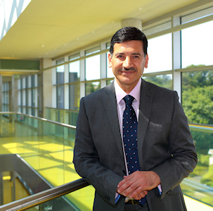
Bashir Mohammed Ali Al-Hashimi, CBE, FREng, FIEEE, FIET, FBCS is the Dean of the Faculty of Natural and Mathematical Sciences, and ARM professor of Computer Engineering at King's College London in the United Kingdom. He is also a Visiting Professor at the School of Electronics and Computer Science (ECS) at the University of Southampton. There, he is the co-director of the ARM-ECS Research Centre, which is an industry-university collaborative centre involving the University of Southampton and ARM. He served as a panel member on the UK Research Excellence Framework (REF) 2014 and is also a member of the REF 2021 Engineering Panel. His research focuses on understanding the interaction between hardware and software in constrained computing systems such as those found in mobile and embedded applications and how such interactions can be used through theory and experiment to achieve systems energy efficiency and enhanced hardware dependability. He has made fundamental contributions to the field of hardware-software co-design, low-power test and test-data compression of digital integrated circuits, and the emerging field of energy-harvesting computing.
References
- ↑ Touba, NA (2006). "Survey of Test Vector Compression Techniques". IEEE Design & Test of Computers. 23 (4): 294–303. doi:10.1109/MDT.2006.105. S2CID 17400003.
- ↑ Rajski, J. and Tyszer, J. and Kassab, M. and Mukherjee, N. (2004). "Embedded deterministic test". IEEE Transactions on Computer-Aided Design of Integrated Circuits and Systems. 23 (5): 776–792. doi:10.1109/TCAD.2004.826558. S2CID 3619228.
{{cite journal}}: CS1 maint: multiple names: authors list (link)