Three-phase AC railway electrification

Last updated
Train using a multiphase electrification system on the Petit train de la Rhune, France Petit train la rhune.jpg
Train using a multiphase electrification system on the Petit train de la Rhune, France

Three-phase AC railway electrification was used in Italy, Switzerland and the United States in the early twentieth century. Italy was the major user, from 1901 until 1976, although lines through two tunnels also used the system; the Simplon Tunnel between Switzerland and Italy from 1906 to 1930 (but not connected to the Italian system), and the Cascade Tunnel of the Great Northern Railway in the United States from 1909 to 1939. The first standard gauge line was in Switzerland, from Burgdorf to Thun (40 km or 25 mi), from 1899 to 1933. [1] [2]

Contents

Advantages

The system provides regenerative braking with the power fed back to the system, so is particularly suitable for mountain railways (provided the grid or another locomotive on the line can accept the power). The locomotives use three-phase induction motors. Lacking brushes and commutators, they require less maintenance. The early Italian and Swiss systems used a low frequency (16+23 Hz), and a relatively low voltage (3,000 or 3,600 volts) compared with later AC systems. (However, both regenerative braking and 16+23 Hz were successfully implemented also for single-phase systems, like for the Swiss Ce 6/8 II and III "Crocodile" type.)

Disadvantages

The overhead wiring, generally having two separate overhead lines and the rail for the third phase, was more complicated, and the low frequency used required a separate generation or conversion and distribution system. Train speed was restricted to one to four speeds, with two or four speeds obtained by pole-changing or cascade operation or both.

Historical systems

The following is a list of the railways that have used this method of electrification in the past: [3]

Current systems

The system is only used today for rack (mountain) railways, where the overhead wiring is less complicated and restrictions on the speeds available less important. Modern motors and their control systems avoid the fixed speeds of traditional systems, as they are built with solid-state converters.

The four current such railways are

All use standard frequency (50 Hz, or 60 Hz (Brazil)) rather than low frequency, using between 725 and 3,000 volts.

Voltage and frequency

This list shows the voltage and frequency used in various systems, historical and current.

Two Italian three-phase locomotives Class E.432 Locomotiva elettrica trifase E 432.031-432.033.jpg
Two Italian three-phase locomotives Class E.432
In some places in Italy, three-phase catenary was reconfigured to work on the standard 3000 V DC electrification scheme in Italy, as seen here at the defunct San Lorenzo al Mare station in Liguria in 1991 (closed 2001). Regular DC catenary is on the left while reconfigured three-phase catenary is on the middle and on the right. San Lorenzo-Cipressa - stazione ferroviaria - E.656.jpg
In some places in Italy, three-phase catenary was reconfigured to work on the standard 3000 V DC electrification scheme in Italy, as seen here at the defunct San Lorenzo al Mare station in Liguria in 1991 (closed 2001). Regular DC catenary is on the left while reconfigured three-phase catenary is on the middle and on the right.

Converter systems

This category does not cover railways with a single-phase (or DC) supply which is converted to three-phase on the locomotive or power car, e.g., most railway equipment from the 1990s and earlier using solid-state converters. The Kando system of the 1930s developed by Kálmán Kandó at the Ganz Works, and used in Hungary and Italy, used rotary phase converters on the locomotive to convert the single-phase supply to three phases, as did the phase-splitting system on the Norfolk and Western Railroad in the United States.

Locomotives

FS Class E.550 (Italy 1906-65) E551-001pietrarsa1999-04-08.jpg
FS Class E.550 (Italy 1906–65)
FS Class E330 (Italy 1914-63). Note the long bow collectors, with their pickup points at the far ends of the locomotive. Mus Scienza Tecnica loco E.330.JPG
FS Class E330 (Italy 1914–63). Note the long bow collectors, with their pickup points at the far ends of the locomotive.

Usually, the locomotives had one, two, or four motors on the body chassis (not on the bogies), and did not require gearing. The induction motors are designed to run at a particular synchronous speed, and when they run above the synchronous speed downhill, power is fed back to the system. Pole changing and cascade (concatenation) working was used to allow two or four different speeds, and resistances (often liquid rheostats) were required for starting. In Italy freight locomotives used plain cascade with two speeds, 25 and 50 km/h (16 and 31 mph); while express locomotives used cascade combined with pole-changing, giving four speeds, 37, 50, 75 and 100 km/h (23, 31, 46 and 62 mph). [2] With the use of 3,000 or 3,600 volts at 16+23 (16.7) Hz, the supply could be fed directly to the motor without an onboard transformer.

Generally, the motor(s) fed a single axle, with other wheels linked by connecting rods, as the induction motor is sensitive to speed variations and with non-linked motors on several axles the motors on worn wheels would do little or even no work as they would rotate faster. [9] This motor characteristic led to a mishap in the Cascade Tunnel to a GN east-bound freight train with four electric locomotives, two on the head and two pushing. The two pushers suddenly lost power and the train gradually slowed to a stop, but the lead unit engineer was unaware that his train had stopped, and held the controller on the power position until the usual time to transit the tunnel had elapsed. Not seeing daylight, he finally shut down the locomotive, and found that the wheels of his stationary locomotive had ground through two-thirds of the rail web. [10]

Overhead wiring

Generally two separate overhead wires are used, with the rail for the third phase, though occasionally three overhead wires are used. At junctions, crossovers and crossings the two lines must be kept apart, with a continuous supply to the locomotive, which must have two live conductors wherever it stops. Hence two collectors per overhead phase are used, but the possibility of bridging a dead section and causing a short circuit from the front collector of one phase to the back collector of the other phase must be avoided. [11] The resistance of the rails used for the third phase or return is higher for AC than for DC due to "skin effect", but lower for the low frequency used than for industrial frequency. Losses are also increased, though not in the same proportion, as the impedance is largely reactive. [12]

3-phase pantograph on a Corcovado Rack Railway train in Brazil Corcovado Bergbahn 2005-03-15.jpg
3-phase pantograph on a Corcovado Rack Railway train in Brazil

The locomotive needs to pick up power from two (or three) overhead conductors. Early locomotives on the Italian State Railways used a wide bow collector which covered both wires but later locomotives used a wide pantograph with two collector bars, side by side. A three-phase system is also prone to larger lengthwise gaps between sections, owing to the complexity of two-wire overhead, and so a long pickup base is needed. In Italy this was achieved with the long bow collectors reaching right to the ends of the locomotive, or with a pair of pantographs, also mounted as far apart as possible. [13]

In the United States, a pair of trolley poles were used. They worked well with a maximum speed of 15 miles per hour (24 km/h). The dual conductor pantograph system is used on four mountain railways that continue to use three-phase power (Corcovado Rack Railway in Rio de Janeiro, Brazil, Jungfraubahn and Gornergratbahn in Switzerland and the Petit train de la Rhune in France).

See also

Footnotes

  1. Middleton (1974), p. 156.
  2. 1 2 Meares & Neale (1933), p. 630-631, para 919
  3. 1 2 Burch (1911), pp. 133–134.
  4. Burch (1911), pp. 349–353.
  5. Burch (1911), pp. 339–342.
  6. Burch (1911), pp. 342–346.
  7. Burch (1911), pp. 471 & 569.
  8. Burch (1911), pp. 346–349.
  9. Starr (1953), p. 347.
  10. Middleton (1974), p. 161.
  11. Maccall (1930), p. 412.
  12. Maccall (1930), p. 423-424.
  13. Hollingsworth & Cook (2000), pp. 56–57.

Related Research Articles

<span class="mw-page-title-main">Locomotive</span> Self-propelled railway vehicle

A locomotive or engine is a rail transport vehicle that provides the motive power for a train. If a locomotive is capable of carrying a payload, it is usually rather referred to as a multiple unit, motor coach, railcar or power car; the use of these self-propelled vehicles is increasingly common for passenger trains, but rare for freight trains.

<span class="mw-page-title-main">Overhead line</span> Cable that provides power to electric railways, trams, and trolleybuses

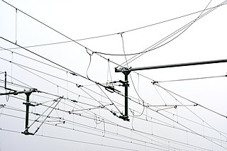
An overhead line or overhead wire is an electrical cable that is used to transmit electrical energy to electric locomotives, trolleybuses or trams. The generic term used by the International Union of Railways for the technology is overhead line. It is known variously as overhead catenary, overhead contact line (OCL), overhead contact system (OCS), overhead equipment (OHE), overhead line equipment, overhead lines (OHL), overhead wiring (OHW), traction wire, and trolley wire.

<span class="mw-page-title-main">Electric locomotive</span> Locomotive powered by electricity

An electric locomotive is a locomotive powered by electricity from overhead lines, a third rail or on-board energy storage such as a battery or a supercapacitor. Locomotives with on-board fuelled prime movers, such as diesel engines or gas turbines, are classed as diesel-electric or gas turbine-electric and not as electric locomotives, because the electric generator/motor combination serves only as a power transmission system.

<span class="mw-page-title-main">Railway electrification</span> Conversion of railways to use electricity for propulsion

Railway electrification is the use of electric power for the propulsion of rail transport. Electric railways use either electric locomotives, electric multiple units or both. Electricity is typically generated in large and relatively efficient generating stations, transmitted to the railway network and distributed to the trains. Some electric railways have their own dedicated generating stations and transmission lines, but most purchase power from an electric utility. The railway usually provides its own distribution lines, switches, and transformers.

<span class="mw-page-title-main">Kálmán Kandó</span> Hungarian engineer and inventor of phase converter (1869-1931)

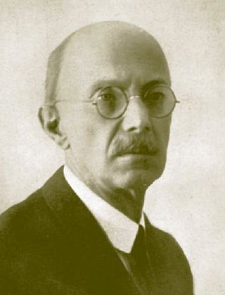
Kálmán Kandó de Egerfarmos et Sztregova was a Hungarian engineer, the inventor of phase converter and a pioneer in the development of AC electric railway traction.

<span class="mw-page-title-main">25 kV AC railway electrification</span> Standard current and voltage settings for most high-speed rail

Railway electrification systems using alternating current (AC) at 25 kilovolts (kV) are used worldwide, especially for high-speed rail. It is usually supplied at the standard utility frequency, which simplifies traction substations. The development of 25 kV AC electrification is closely connected with that of successfully using utility frequency.

<span class="mw-page-title-main">15 kV AC railway electrification</span> Standard current and voltage settings for much of Central Europes train transport

Railway electrification using alternating current (AC) at 15 kilovolts (kV) and 16.7 hertz (Hz) are used on transport railways in Germany, Austria, Switzerland, Sweden, and Norway. The high voltage enables high power transmission with the lower frequency reducing the losses of the traction motors that were available at the beginning of the 20th century. Railway electrification in late 20th century tends to use 25 kV, 50 Hz AC systems which has become the preferred standard for new railway electrifications but extensions of the existing 15 kV networks are not completely unlikely. In particular, the Gotthard Base Tunnel still uses 15 kV, 16.7 Hz electrification.

Railroad electrification in the United States began at the turn of the 20th century and comprised many different systems in many different geographical areas, few of which were connected. Despite this situation, these systems shared a small number of common reasons for electrification.

<span class="mw-page-title-main">FS Class E.550</span>

The FS Class E.550 was a class of three-phase electric locomotive used in Italy, introduced in the 20th century, which remained in service until 1965.

<span class="mw-page-title-main">FS Class E.330</span>

The FS Class E.330 was a small class of three-phase electric locomotive used in Italy, introduced in the 1910s.

<span class="mw-page-title-main">Electrification of the New York, New Haven and Hartford Railroad</span>

The New York, New Haven and Hartford Railroad pioneered electrification of main line railroads using high-voltage, alternating current, single-phase overhead catenary. It electrified its mainline between Stamford, Connecticut, and Woodlawn, New York, in 1907 and extended the electrification to New Haven, Connecticut, in 1914. While single-phase AC railroad electrification has become commonplace, the New Haven's system was unprecedented at the time of construction. The significance of this electrification was recognized in 1982 by its designation as a Historic Mechanical Engineering Landmark by the American Society of Mechanical Engineers (ASME).

<span class="mw-page-title-main">Baldwin-Westinghouse electric locomotives</span>

Baldwin, the locomotive manufacturer, and Westinghouse, the promoter of AC electrification, joined forces in 1895 to develop AC railway electrification. Soon after the turn of the century, they marketed a single-phase high-voltage system to railroads. From 1904 to 1905 they supplied locomotives carrying a joint builder's plate to a number of American railroads, particularly for the New Haven line from New York to New Haven, and other New Haven lines. Westinghouse would produce the motors, controls, and other electrical gear, while Baldwin would produce the running gear, frame, body, and perform final assembly.

<span class="mw-page-title-main">Seebach-Wettingen railway electrification trial</span>

The Seebach-Wettingen railway electrification trial (1905-1909) was an important milestone in the development of electric railways. Maschinenfabrik Oerlikon (MFO) demonstrated the suitability of single-phase alternating current at high voltage for long-distance railway operation with the Seebach-Wettingen single-phase alternating current test facility. For this purpose, MFO electrified the 19.45-kilometre-long Swiss Federal Railways (SBB) route from Seebach to Wettingen at its own expense with single-phase alternating current at 15,000 volts.

<span class="mw-page-title-main">FS Class E.360</span>

The FS Class E.360 were electric locomotives of the Italian State Railways (FS), using three-phase alternating current, built for the operation of the Valtellina line. They were ordered by Rete Adriatica and were originally numbered RA 361–363. Italian railways were nationalized in 1905 and they then became FS E.361-363 They were leased to Swiss Federal Railways (SBB) in 1906 and returned to Italy in 1907.

The FS Class E.470 was an electric locomotive class of the state-owned Italian railway Ferrovie dello Stato. It was used on the Italian three-phase test line from Rome-Sulmona especially in express train service. After the end of the trial operation in 1945, the locomotives were scrapped, and no locomotive of the class has been preserved.

<span class="mw-page-title-main">Ferrovia della Valtellina</span>

The Ferrovia della Valtellina is a railway line in Italy that runs from Lecco to Valtellina and Valchiavenna. It was opened in 1894 and electrified on the three-phase system in 1902. It is now electrified at 3 kV direct current and operated by Trenord.

<span class="mw-page-title-main">FS Class E.430</span>

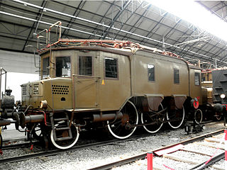
The FS Class E.430 locomotives, initially classed as RA 34, were three-phase alternating current electric locomotives of the Italian railways. They were built for Ferrovia della Valtellina by Ganz and MÁVAG in 1901 and had a power output of 440 kW and a haulage capacity of 300 tons. One locomotive is preserved.

<span class="mw-page-title-main">Great Northern Z-1</span>

The Great Northern Z-1 was a class of ten electric locomotives built for the Great Northern Railway They were used to work the route through the second Cascade Tunnel. They were built between 1926–1928 by Baldwin Locomotive Works, with Westinghouse electrics, and stayed in service until dieselisation in 1956. Each was of 1,830 horsepower (1,360 kW) with a 1-D-1 wheel arrangement, although they were always used in coupled pairs.

<span class="mw-page-title-main">Rigid-framed electric locomotive</span>

Rigid-framed electric locomotives were some of the first generations of electric locomotive design. When these began the traction motors of these early locomotives, particularly with AC motors, were too large and heavy to be mounted directly to the axles and so were carried on the frame. One of the initial simplest wheel arrangements for a mainline electric locomotive, from around 1900, was the 1′C1′ arrangement, in UIC classification.

<span class="mw-page-title-main">DB Class E 410</span> German electric locomotive

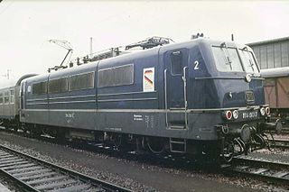
The DB Class E 410 locomotive of the German Federal Railroad (DB), also known as DB Class 184, was one of the first four-current electric locomotives provided for international services from Germany to France, Belgium, Luxembourg and the Netherlands.

References

Commons-logo.svg Media related to Three-phase electrifications at Wikimedia Commons