Schematic diagram of a turboexpander driving a compressor
A turboexpander, also referred to as a turbo-expander or an expansion turbine, is a centrifugal or axial-flow turbine, through which a high-pressuregas is expanded to produce work that is often used to drive a compressor or generator.[1][2][3]
Because work is extracted from the expanding high-pressure gas, the expansion is approximated by an isentropic process (i.e., a constant-entropy process), and the low-pressure exhaust gas from the turbine is at a very low temperature, −150°C or less, depending upon the operating pressure and gas properties. Partial liquefaction of the expanded gas is not uncommon.
Turboexpanders currently in operation range in size from about 750 W to about 7.5 MW (1 hp to about 10,000hp) [citation needed].
Applications
Although turboexpanders are commonly used in low-temperature processes, they are used in many other applications. This section discusses one of the low-temperature processes, as well as some of the other applications.
Extracting hydrocarbon liquids from natural gas
A schematic diagram of a demethanizer extracting hydrocarbon liquids from natural gas
When processed into finished by-products (see Natural-gas processing), these heavier hydrocarbons are collectively referred to as NGL (natural-gas liquids). The extraction of the NGL often involves a turboexpander[7] and a low-temperature distillation column (called a demethanizer) as shown in the figure. The inlet gas to the demethanizer is first cooled to about −51°C in a heat exchanger (referred to as a cold box), which partially condenses the inlet gas. The resultant gas–liquid mixture is then separated into a gas stream and a liquid stream.
The liquid stream from the gas–liquid separator flows through a valve and undergoes a throttling expansion from an absolute pressure of 62 bar to 21 bar (6.2 to 2.1 MPa), which is an isenthalpic process (i.e., a constant-enthalpy process) that results in lowering the temperature of the stream from about −51°C to about −81°C as the stream enters the demethanizer.
The gas stream from the gas–liquid separator enters the turboexpander, where it undergoes an isentropic expansion from an absolute pressure of 62 bar to 21 bar (6.2 to 2.1 MPa) that lowers the gas stream temperature from about −51°C to about −91°C as it enters the demethanizer to serve as distillation reflux.
Liquid from the top tray of the demethanizer (at about −90°C) is routed through the cold box, where it is warmed to about 0°C as it cools the inlet gas, and is then returned to the lower section of the demethanizer. Another liquid stream from the lower section of the demethanizer (at about 2°C) is routed through the cold box and returned to the demethanizer at about 12°C. In effect, the inlet gas provides the heat required to "reboil" the bottom of the demethanizer, and the turboexpander removes the heat required to provide reflux in the top of the demethanizer.
The overhead gas product from the demethanizer at about −90°C is processed natural gas that is of suitable quality for distribution to end-use consumers by pipeline. It is routed through the cold box, where it is warmed as it cools the inlet gas. It is then compressed in the gas compressor driven by the turboexpander and further compressed in a second-stage gas compressor driven by an electric motor before entering the distribution pipeline.
The bottom product from the demethanizer is also warmed in the cold box, as it cools the inlet gas, before it leaves the system as NGL.
The operating conditions of an offshore gas conditioning turbo-expander/recompressor are as follows:[8]
Turbo-expander
Recompressor
Inlet
Outlet
Inlet
Outlet
Temperature °C
11.0
–13.0
22.0
40.0
Pressure barg
75.0
39.31
38.62
47.24
Flow kg/hr
27728
20658
Molecular weight
22.08
20.74
Energy recovered/used kW
345
345
Power generation
Schematic diagram of power-generation system using a turboexpander
The figure depicts an electric power-generation system that uses a heat source, a cooling medium (air, water or other), a circulating working fluid and a turboexpander. The system can accommodate a wide variety of heat sources such as:
a variety of waste heat sources (in the form of either gas or liquid).
The circulating working fluid (usually an organic compound such as R-134a) is pumped to a high pressure and then vaporized in the evaporator by heat exchange with the available heat source. The resulting high-pressure vapor flows to the turboexpander, where it undergoes an isentropic expansion and exits as a vapor–liquid mixture, which is then condensed into a liquid by heat exchange with the available cooling medium. The condensed liquid is pumped back to the evaporator to complete the cycle.
The system in the figure implements a Rankine cycle as it is used in fossil-fuel power plants, where water is the working fluid and the heat source is derived from the combustion of natural gas, fuel oil or coal used to generate high-pressure steam. The high-pressure steam then undergoes an isentropic expansion in a conventional steam turbine. The steam turbine exhaust steam is next condensed into liquid water, which is then pumped back to steam generator to complete the cycle.
When an organic working fluid such as R-134a is used in the Rankine cycle, the cycle is sometimes referred to as an organic Rankine cycle (ORC).[9][10][11]
Refrigeration system
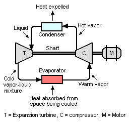
Schematic diagram of a refrigeration system using a turboexpander, compressor and a motor
A refrigeration system utilizes a compressor, a turboexpander and an electric motor.
Depending on the operating conditions, the turboexpander reduces the load on the electric motor by 6–15% compared to a conventional vapor-compression refrigeration system that uses a throttling expansion valve rather than a turboexpander.[12] Basically, this can be seen as a form of turbo compounding.
The system employs a high-pressure refrigerant (i.e., one with a low normal boiling point) such as:[12]
As shown in the figure, refrigerant vapor is compressed to a higher pressure, resulting in a higher temperature as well. The hot, compressed vapor is then condensed into a liquid. The condenser is where heat is expelled from the circulating refrigerant and is carried away by whatever cooling medium is used in the condenser (air, water, etc.).
The refrigerant liquid flows through the turboexpander, where it is vaporized, and the vapor undergoes an isentropic expansion, which results in a low-temperature mixture of vapor and liquid. The vapor–liquid mixture is then routed through the evaporator, where it is vaporized by heat absorbed from the space being cooled. The vaporized refrigerant flows to the compressor inlet to complete the cycle.
In the case where the working fluid remains gaseous into the heat exchangers without undergoing phase changes, this cycle is also referred to as reverse Brayton cycle or "refrigerating Brayton cycle".
Power recovery in fluid catalytic cracker
A schematic diagram of the power recovery system in a fluid catalytic cracking unit
The combustionflue gas from the catalyst regenerator of a fluid catalytic cracker is at a temperature of about 715°C and at a pressure of about 2.4 barg (240 kPa gauge). Its gaseous components are mostly carbon monoxide (CO), carbon dioxide (CO2) and nitrogen (N2). Although the flue gas has been through two stages of cyclones (located within the regenerator) to remove entrained catalyst fines, it still contains some residual catalyst fines.
The figure depicts how power is recovered and utilized by routing the regenerator flue gas through a turboexpander. After the flue gas exits the regenerator, it is routed through a secondary catalyst separator containing swirl tubes designed to remove 70–90% of the residual catalyst fines.[13] This is required to prevent erosion damage to the turboexpander.
As shown in the figure, expansion of the flue gas through a turboexpander provides sufficient power to drive the regenerator's combustion air compressor. The electrical motor-generator in the power-recovery system can consume or produce electrical power. If the expansion of the flue gas does not provide enough power to drive the air compressor, the electric motor-generator provides the needed additional power. If the flue gas expansion provides more power than needed to drive the air compressor, then the electric motor-generator converts the excess power into electric power and exports it to the refinery's electrical system.[14] The steam turbine is used to drive the regenerator's combustion air compressor during start-ups of the fluid catalytic cracker until there is sufficient combustion flue gas to take over that task.
The expanded flue gas is then routed through a steam-generating boiler (referred to as a CO boiler), where the carbon monoxide in the flue gas is burned as fuel to provide steam for use in the refinery.[14]
The possible use of an expansion machine for isentropically creating low temperatures was suggested by Carl Wilhelm Siemens (Siemens cycle), a German engineer in 1857. About three decades later, in 1885, Ernest Solvay of Belgium attempted to use a reciprocating expander machine, but could not attain any temperatures lower than −98°C because of problems with lubrication of the machine at such temperatures.[2]
In 1902, Georges Claude, a French engineer, successfully used a reciprocating expansion machine to liquefy air. He used a degreased, burnt leather packing as a piston seal without any lubrication. With an air pressure of only 40 bar (4 MPa), Claude achieved an almost isentropic expansion resulting in a lower temperature than had before been possible.[2]
The first turboexpanders seem to have been designed in about 1934 or 1935 by Guido Zerkowitz, an Italian engineer working for the German firm of Linde AG.[15][16]
In 1939, the Russian physicist Pyotr Kapitsa perfected the design of centrifugal turboexpanders. His first practical prototype was made of Monel metal, had an outside diameter of only 8cm (3.1in), operated at 40,000 revolutions per minute and expanded 1,000 cubic metres of air per hour. It used a water pump as a brake and had an efficiency of 79–83%.[2][16] Most turboexpanders in industrial use since then have been based on Kapitsa's design, and centrifugal turboexpanders have taken over almost 100% of the industrial gas liquefaction and low-temperature process requirements.[2][16] The availability of liquid oxygen revolutionized the production of steel using the basic oxygen steelmaking process.
In 1978, Pyotr Kapitsa was awarded a Nobel physics prize for his body of work in the area of low-temperature physics.[17]
In 1983, San Diego Gas and Electric was among the first to install a turboexpander in a natural-gas letdown station for energy recovery.[18]
Types
Turboexpanders can be classified by loading device or bearings.
Three main loading devices used in turboexpanders are centrifugal compressors, electrical generators or hydraulic brakes. With centrifugal compressors and electrical generators the shaft power from the turboexpander is recouped either to recompress the process gas or to generate electrical energy, lowering utility bills.
Hydraulic brakes are used when the turboexpander is very small and harvesting the shaft power is not economically justifiable.
↑Gas Processes 2002, Hydrocarbon Processing, pages 83–84, May 2002 (schematic flow diagrams and descriptions of the NGL-Pro and NGL recovery processes).
12Refrigeration apparatus with expansion turbine, European patent EP 0 676 600 B1, September 6, 2000, Joost J. Brasz, Carrier Corporation EP 0 676 600 B1 (this website requires registration).
↑Alex C. Hoffnab and Lewis E. Stein (2002). Gas Cyclones and Swirl Tubes: Principles, Design and Operation (1sted.). Springer. ISBN3-540-43326-0.
↑Turbine for Low Temperature Gas Separation, U.S. Patent 2,165,994, July 1939 (Continuation of an application in March 1934), Guido Zerkowitz, Linde AG United States Patent US2165994 (this website requires registration).
123Ebbe Almqvist (2002). History of Industrial Gases (Firsted.). Springer. p.165. ISBN0-306-47277-5.
This page is based on this Wikipedia article Text is available under the CC BY-SA 4.0 license; additional terms may apply. Images, videos and audio are available under their respective licenses.