Related Research Articles
The unified modeling language (UML) is a general-purpose visual modeling language that is intended to provide a standard way to visualize the design of a system.
The XML Metadata Interchange (XMI) is an Object Management Group (OMG) standard for exchanging metadata information via Extensible Markup Language (XML).
A modeling language is any artificial language that can be used to express data, information or knowledge or systems in a structure that is defined by a consistent set of rules. The rules are used for interpretation of the meaning of components in the structure of a programming language.
Model-driven architecture (MDA) is a software design approach for the development of software systems. It provides a set of guidelines for the structuring of specifications, which are expressed as models. Model Driven Architecture is a kind of domain engineering, and supports model-driven engineering of software systems. It was launched by the Object Management Group (OMG) in 2001.
The Object Constraint Language (OCL) is a declarative language describing rules applying to Unified Modeling Language (UML) models developed at IBM and is now part of the UML standard. Initially, OCL was merely a formal specification language extension for UML. OCL may now be used with any Meta-Object Facility (MOF) Object Management Group (OMG) meta-model, including UML. The Object Constraint Language is a precise text language that provides constraint and object query expressions on any MOF model or meta-model that cannot otherwise be expressed by diagrammatic notation. OCL is a key component of the new OMG standard recommendation for transforming models, the Queries/Views/Transformations (QVT) specification.
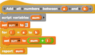
In computing, a visual programming language, also known as diagrammatic programming, graphical programming or block coding, is a programming language that lets users create programs by manipulating program elements graphically rather than by specifying them textually. A VPL allows programming with visual expressions, spatial arrangements of text and graphic symbols, used either as elements of syntax or secondary notation. For example, many VPLs are based on the idea of "boxes and arrows", where boxes or other screen objects are treated as entities, connected by arrows, lines or arcs which represent relations. VPLs are generally the basis of low-code development platforms.

A flowchart is a type of diagram that represents a workflow or process. A flowchart can also be defined as a diagrammatic representation of an algorithm, a step-by-step approach to solving a task.
Round-trip engineering (RTE) in the context of model-driven architecture is a functionality of software development tools that synchronizes two or more related software artifacts, such as, source code, models, configuration files, documentation, etc. between each other. The need for round-trip engineering arises when the same information is present in multiple artifacts and when an inconsistency may arise in case some artifacts are updated. For example, some piece of information was added to/changed in only one artifact and, as a result, it became missing in/inconsistent with the other artifacts.
The common warehouse metamodel (CWM) defines a specification for modeling metadata for relational, non-relational, multi-dimensional, and most other objects found in a data warehousing environment. The specification is released and owned by the Object Management Group, which also claims a trademark in the use of "CWM".

A metamodel is a model of a model, and metamodeling is the process of generating such metamodels. Thus metamodeling or meta-modeling is the analysis, construction, and development of the frames, rules, constraints, models, and theories applicable and useful for modeling a predefined class of problems. As its name implies, this concept applies the notions of meta- and modeling in software engineering and systems engineering. Metamodels are of many types and have diverse applications.
Object-oriented analysis and design (OOAD) is a technical approach for analyzing and designing an application, system, or business by applying object-oriented programming, as well as using visual modeling throughout the software development process to guide stakeholder communication and product quality.
Model-driven engineering (MDE) is a software development methodology that focuses on creating and exploiting domain models, which are conceptual models of all the topics related to a specific problem. Hence, it highlights and aims at abstract representations of the knowledge and activities that govern a particular application domain, rather than the computing concepts.

ATL is a model transformation language and toolkit developed and maintained by OBEO and AtlanMod. It was initiated by the AtlanMod team. In the field of Model-Driven Engineering (MDE), ATL provides ways to produce a set of target models from a set of source models.
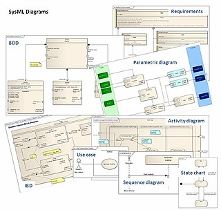
The systems modeling language (SysML) is a general-purpose modeling language for systems engineering applications. It supports the specification, analysis, design, verification and validation of a broad range of systems and systems-of-systems.
The Business Process Definition Metamodel (BPDM) is a standard definition of concepts used to express business process models, adopted by the OMG. Metamodels define concepts, relationships, and semantics for exchange of user models between different modeling tools. The exchange format is defined by XSD and XMI, a specification for transformation of OMG metamodels to XML. Pursuant to the OMG's policies, the metamodel is the result of an open process involving submissions by member organizations, following a Request for Proposal (RFP) issued in 2003. BPDM was adopted in initial form in July 2007, and finalized in July 2008.

UModel is a UML software modeling tool from Altova, the creator of XMLSpy. UModel supports all 14 UML 2 diagram types and adds a unique diagram for modeling XML Schemas in UML. UModel also supports SysML for embedded system developers, and business process modeling for enterprise analysts. UModel includes code engineering functionality including code generation in Java, C#, and Visual Basic, reverse engineering of existing applications, and round-trip engineering.
UML is a modeling language used by software developers. UML can be used to develop diagrams and provide users (programmers) with ready-to-use, expressive modeling examples. Some UML tools generate program language code from UML. UML can be used for modeling a system independent of a platform language. UML is a graphical language for visualizing, specifying, constructing, and documenting information about software-intensive systems. UML gives a standard way to write a system model, covering conceptual ideas. With an understanding of modeling, the use and application of UML can make the software development process more efficient.
The Interaction Flow Modeling Language (IFML) is a standardized modeling language in the field of software engineering. IFML includes a set of graphic notations to create visual models of user interactions and front-end behavior in software systems.
Umple is a language for both object-oriented programming and modelling with class diagrams and state diagrams. The name Umple is a portmanteau of "UML", "ample" and "Simple", indicating that it is designed to provide ample features to extend programming languages with UML capabilities.

Sparx Systems Enterprise Architect is a visual modeling and design tool based on the OMG UML. The platform supports: the design and construction of software systems; modeling business processes; and modeling industry based domains. It is used by businesses and organizations to not only model the architecture of their systems, but to process the implementation of these models across the full application development life-cycle.
References
- ↑ http://www.developerdotstar.com/mag/articles/reeves_design_main.html by Jack W. Reeves