The Universal Mobile Telecommunications System (UMTS) is a third generation mobile cellular system for networks based on the GSM standard. Developed and maintained by the 3GPP, UMTS is a component of the International Telecommunication Union IMT-2000 standard set and compares with the CDMA2000 standard set for networks based on the competing cdmaOne technology. UMTS uses wideband code-division multiple access (W-CDMA) radio access technology to offer greater spectral efficiency and bandwidth to mobile network operators.

The 3rd Generation Partnership Project (3GPP) is an umbrella term for a number of standards organizations which develop protocols for mobile telecommunications. Its best known work is the development and maintenance of:
In the Universal Mobile Telecommunications System (UMTS) and 3GPP Long Term Evolution (LTE), user equipment (UE) is any device used directly by an end-user to communicate. It can be a hand-held telephone, a laptop computer equipped with a mobile broadband adapter, or any other device. It connects to the base station Node B/eNodeB as specified in the ETSI 125/136-series and 3GPP 25/36-series of specifications. It roughly corresponds to the mobile station (MS) in GSM systems.
The GPRS core network is the central part of the general packet radio service (GPRS) which allows 2G, 3G and WCDMA mobile networks to transmit Internet Protocol (IP) packets to external networks such as the Internet. The GPRS system is an integrated part of the GSM network switching subsystem.
The Radio Network Controller (RNC) is a governing element in the UMTS radio access network (UTRAN) and is responsible for controlling the Node Bs that are connected to it. The RNC carries out radio resource management, some of the mobility management functions and is the point where encryption is done before user data is sent to and from the mobile. The RNC connects to the Circuit Switched Core Network through Media Gateway (MGW) and to the SGSN in the Packet Switched Core Network.
In telecommunications networks, RANAP is a protocol specified by 3GPP in TS 25.413 and used in UMTS for signaling between the Core Network, which can be a MSC or SGSN, and the UTRAN. RANAP is carried over Iu-interface.

Node B is the telecommunications node for mobile communication networks, namely those that adhere to the UMTS standard. The Node B provides the connection between mobile phones (UEs) and the wider telephone network. UMTS is the dominating 3G standard.
Multimedia Broadcast Multicast Services (MBMS) is a point-to-multipoint interface specification for existing 3GPP cellular networks, which is designed to provide efficient delivery of broadcast and multicast services, both within a cell as well as within the core network. For broadcast transmission across multiple cells, it defines transmission via single-frequency network configurations. The specification is referred to as Evolved Multimedia Broadcast Multicast Services (eMBMS) when transmissions are delivered through an LTE network. eMBMS is also known as LTE Broadcast.
RNSAP is a 3GPP signalling protocol responsible for communications between RNCs Radio Network Controllers defined in 3GPP specification TS 25.423. It is carried on the lur interface and provides functionality needed for soft handovers and SRNS relocation. It defines signalling between RNCs, including SRNC and DRNC.
SRNC | DRNC | IUR | RNSAP | RNSAP | | |
A radio access network (RAN) is part of a mobile telecommunication system implementing a radio access technology (RAT). Conceptually, it resides between a device such as a mobile phone, a computer, or any remotely controlled machine and provides connection with its core network (CN). Depending on the standard, mobile phones and other wireless connected devices are varyingly known as user equipment (UE), terminal equipment, mobile station (MS), etc. RAN functionality is typically provided by a silicon chip residing in both the core network as well as the user equipment. See the following diagram:
CN / ⧵ / ⧵ RAN RAN / ⧵ / ⧵ UE UE UE UE
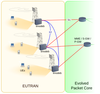
E-UTRA is the air interface of 3rd Generation Partnership Project (3GPP) Long Term Evolution (LTE) upgrade path for mobile networks. It is an acronym for Evolved UMTS Terrestrial Radio Access, also known as the Evolved Universal Terrestrial Radio Access in early drafts of the 3GPP LTE specification. E-UTRAN is the combination of E-UTRA, user equipment (UE), and a Node B.

In telecommunications, a femtocell is a small, low-power cellular base station, typically designed for use in a home or small business. A broader term which is more widespread in the industry is small cell, with femtocell as a subset. It typically connects to the service provider's network via the Internet through a wired broadband link ; current designs typically support four to eight simultaneously active mobile phones in a residential setting depending on version number and femtocell hardware, and eight to sixteen mobile phones in enterprise settings. A femtocell allows service providers to extend service coverage indoors or at the cell edge, especially where access would otherwise be limited or unavailable. Although much attention is focused on WCDMA, the concept is applicable to all standards, including GSM, CDMA2000, TD-SCDMA, WiMAX and LTE solutions.

Due to economy of scale property of telecommunication industry, sharing of telecom infrastructure among telecom service providers is becoming the requirement and process of business in the telecom industry where competitors are becoming partners in order to lower their increasing investments. The degree and method of infrastructure sharing can vary in each country depending on regulatory and competitive climate.
System Architecture Evolution (SAE) is the core network architecture of mobile communications protocol group 3GPP's LTE wireless communication standard.
A Home Node B, or HNB, is the 3GPP's term for a 3G femtocell or Small Cell.
The Mobile Telephone Switching Office (MTSO) is the mobile equivalent of a PSTN Central Office. The MTSO contains the switching equipment or Mobile Switching Center (MSC) for routing mobile phone calls. It also contains the equipment for controlling the cell sites that are connected to the MSC.
ATM Adaptation Layer 2 (AAL2) is an Asynchronous Transfer Mode (ATM) adaptation layer, used primarily in telecommunications; for example, it is used for the Iu interfaces in the Universal Mobile Telecommunications System, and is also used for transporting digital voice. The standard specifications related to AAL2 are ITU standards I.363.2 and I366.1.
HNBAP is a control protocol found in Home Node B networks on the Iu-h interface.
The UMTS channels are communication channels used by third generation (3G) wireless Universal Mobile Telecommunications System (UMTS) networks. UMTS channels can be divided into three levels:

E-UTRAN Node B, also known as Evolved Node B, is the element in E-UTRA of LTE that is the evolution of the element Node B in UTRA of UMTS. It is the hardware that is connected to the mobile phone network that communicates directly wirelessly with mobile handsets (UEs), like a base transceiver station (BTS) in GSM networks.
