
A fluid flowing around an object exerts a force on it. Lift is the component of this force that is perpendicular to the oncoming flow direction. It contrasts with the drag force, which is the component of the force parallel to the flow direction. Lift conventionally acts in an upward direction in order to counter the force of gravity, but it can act in any direction at right angles to the flow.

A wing is a type of fin that produces lift while moving through air or some other fluid. Accordingly, wings have streamlined cross-sections that are subject to aerodynamic forces and act as airfoils. A wing's aerodynamic efficiency is expressed as its lift-to-drag ratio. The lift a wing generates at a given speed and angle of attack can be one to two orders of magnitude greater than the total drag on the wing. A high lift-to-drag ratio requires a significantly smaller thrust to propel the wings through the air at sufficient lift.

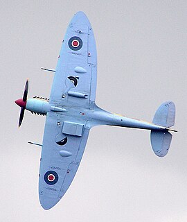
A fixed-wing aircraft is a heavier-than-air flying machine, such as an airplane, which is capable of flight using wings that generate lift caused by the aircraft's forward airspeed and the shape of the wings. Fixed-wing aircraft are distinct from rotary-wing aircraft, and ornithopters. The wings of a fixed-wing aircraft are not necessarily rigid; kites, hang gliders, variable-sweep wing aircraft and airplanes that use wing morphing are all examples of fixed-wing aircraft.

In aeronautics, the chord is an imaginary straight line joining the leading edge and trailing edge of an aerofoil. The chord length is the distance between the trailing edge and the point where the chord intersects the leading edge. The point on the leading edge used to define the chord may be the surface point of minimum radius. For a turbine aerofoil the chord may be defined by the line between points where the front and rear of a 2-dimensional blade section would touch a flat surface when laid convex-side up.

An airfoil or aerofoil is the cross-sectional shape of an object whose motion through a gas is capable of generating significant lift, such as a wing, a sail, or the blades of propeller, rotor, or turbine.

In aerodynamics, the lift-to-drag ratio is the lift generated by an aerodynamic body such as an aerofoil or aircraft, divided by the aerodynamic drag caused by moving through air. It describes the aerodynamic efficiency under given flight conditions. The L/D ratio for any given body will vary according to these flight conditions.

In aircraft design and aerospace engineering, a high-lift device is a component or mechanism on an aircraft's wing that increases the amount of lift produced by the wing. The device may be a fixed component, or a movable mechanism which is deployed when required. Common movable high-lift devices include wing flaps and slats. Fixed devices include leading-edge slots, leading edge root extensions, and boundary layer control systems.

A flap is a high-lift device used to reduce the stalling speed of an aircraft wing at a given weight. Flaps are usually mounted on the wing trailing edges of a fixed-wing aircraft. Flaps are used to reduce the take-off distance and the landing distance. Flaps also cause an increase in drag so they are retracted when not needed.

A paper plane is a toy aircraft, usually a glider made out of single folded sheet of paper or paperboard. A simple nose-heavy paper plane, thrown like a dart, is also known as a paper dart.
In aeronautics and aeronautical engineering, camber is the asymmetry between the two acting surfaces of an airfoil, with the top surface of a wing commonly being more convex. An airfoil that is not cambered is called a symmetric airfoil. The benefits of cambering were discovered and first utilized by George Cayley in the early 19th century.

A wingsail, twin-skin sail or double skin sail is a variable-camber aerodynamic structure that is fitted to a marine vessel in place of conventional sails. Wingsails are analogous to airplane wings, except that they are designed to provide lift on either side to accommodate being on either tack. Whereas wings adjust camber with flaps, wingsails adjust camber with a flexible or jointed structure. Wingsails are typically mounted on an unstayed spar—often made of carbon fiber for lightness and strength. The geometry of wingsails provides more lift, and a better lift-to-drag ratio, than traditional sails. Wingsails are more complex and expensive than conventional sails.
An adaptive compliant wing is a wing which is flexible enough for aspects of its shape to be changed in flight. Flexible wings have a number of benefits. Conventional flight control mechanisms operate using hinges, resulting in disruptions to the airflow, vortices, and in some cases, separation of the airflow. These effects contribute to the drag of the aircraft, resulting in less efficiency and higher fuel costs. Flexible aerofoils can manipulate aerodynamic forces with less disruptions to the flow, resulting in less aerodynamic drag and improved fuel economy.
The wing configuration of a fixed-wing aircraft is its arrangement of lifting and related surfaces.
Slats are aerodynamic surfaces on the leading edge of the wings of fixed-wing aircraft which, when deployed, allow the wing to operate at a higher angle of attack. A higher coefficient of lift is produced as a result of angle of attack and speed, so by deploying slats an aircraft can fly at slower speeds, or take off and land in shorter distances. They are usually used while landing or performing maneuvers which take the aircraft close to a stall, but are usually retracted in normal flight to minimize drag. They decrease stall speed.
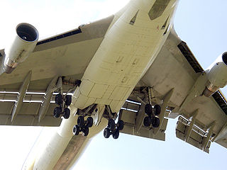
Krueger flaps, or Krüger flaps, are lift enhancement devices that may be fitted to the leading edge of an aircraft wing. Unlike slats or droop flaps, the main wing upper surface and its nose is not changed. Instead, a portion of the lower wing is rotated out in front of the main wing leading edge. Several modern aircraft use this design between the fuselage and closest engine, where the wing is thickest. Outboard of the engine, slats are used on the leading edge. The Boeing 727 also used a mix of inboard Krueger flaps and outboard slats, although it had no engine between them. Most early jet airliners, such as the Boeing 707 and Boeing 747, used Krueger flaps only.
The Akaflieg Darmstadt D-30 Cirrus was an aerodynamically advanced single seat sailplane with a very high aspect ratio wing and a pod and boom fuselage. Built in Germany just before World War II, it was intended as a record breaker and duly set a new world out-and-return distance record in 1938.
The Akaflieg Darmstadt D-40 is an experimental variable geometry single seat sailplane, fitted with almost full span, camber changing flaps for optimum aerodynamics in weak thermals and integrated into the wing so as to minimise flap tip drag. One flew successfully but the D-40, like other variable geometry sailplanes, was not commercialised.
The Akaflieg Braunschweig SB-11 is an experimental, single seat, variable geometry sailplane designed by aeronautical students in Germany. It won the 15 m span class at the World Gliding Championships of 1978 but its advances over the best, more conventional, opposition were not sufficient to lead to widespread imitation.

The SZD-42 Jantar 2 is a single seat Open Class competition glider, designed and produced in Poland in the 1970s. It features a span of over 20 m (66 ft) and elastic, camber changing flaps. It was placed second, third and seventh at the 1976 World Gliding Championships. Over one hundred were built and more than ninety remain registered.

The leading-edge droop flap is a device on the leading edge of aircraft wings designed to improve airflow at high pitch angles. The droop flap is similar to the leading-edge slat and the Krueger flap, but with the difference that the entire leading edge section rotates downwards, whereas the slat and Krueger flap are panels which move away from the wing leading edge when it is deployed.