Related Research Articles

A power inverter, inverter, or invertor is a power electronic device or circuitry that changes direct current (DC) to alternating current (AC). The resulting AC frequency obtained depends on the particular device employed. Inverters do the opposite of rectifiers which were originally large electromechanical devices converting AC to DC.

A Flexible Alternating Current Transmission System (FACTS) is a family of Power-Electronic based devices designed for use on an Alternating Current (AC) Transmission System to improve and control Power Flow and support Voltage. FACTs devices are alternatives to traditional electric grid solutions and improvements, where building additional Transmission Lines or Substation is not economically or logistically viable.

Power electronics is the application of electronics to the control and conversion of electric power.

A variable-frequency drive is a type of AC motor drive that controls speed and torque by varying the frequency of the input electricity. Depending on its topology, it controls the associated voltage or current variation.
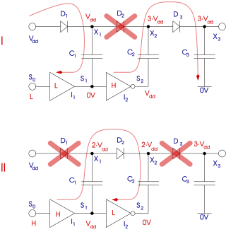
A charge pump is a kind of DC-to-DC converter that uses capacitors for energetic charge storage to raise or lower voltage. Charge-pump circuits are capable of high efficiencies, sometimes as high as 90–95%, while being electrically simple circuits.
This is an alphabetical list of articles pertaining specifically to electrical and electronics engineering. For a thematic list, please see List of electrical engineering topics. For a broad overview of engineering, see List of engineering topics. For biographies, see List of engineers.

Maximum power point tracking (MPPT), or sometimes just power point tracking (PPT), is a technique used with variable power sources to maximize energy extraction as conditions vary. The technique is most commonly used with photovoltaic (PV) solar systems but can also be used with wind turbines, optical power transmission and thermophotovoltaics.
Islanding is the intentional or unintentional division of an interconnected power grid into individual disconnected regions with their own power generation.

In Electrical Engineering, a static synchronous compensator (STATCOM) is a shunt-connected, reactive compensation device used on transmission networks. It uses power electronics to form a voltage-source converter that can act as either a source or sink of reactive AC power to an electricity network. It is a member of the FACTS family of devices.
In the field of EMC, active EMI reduction refers to techniques aimed to reduce or to filter electromagnetic noise (EMI) making use of active electronic components. Active EMI reduction contrasts with passive filtering techniques, such as RC filters, LC filters RLC filters, which includes only passive electrical components. Hybrid solutions including both active and passive elements exist. Standards concerning conducted and radiated emissions published by IEC and FCC set the maximum noise level allowed for different classes of electrical devices. The frequency range of interest spans from 150 kHz to 30 MHz for conducted emissions and from 30 MHz to 40 GHz for radiated emissions. Meeting these requirements and guaranteeing the functionality of an electrical apparatus subject to electromagnetic interference are the main reason to include an EMI filter. In an electrical system, power converters, i.e. DC/DC converters, inverters and rectifiers, are the major sources of conducted EMI, due to their high-frequency switching ratio which gives rise to unwanted fast current and voltage transients. Since power electronics is nowadays spread in many fields, from power industrial application to automotive industry, EMI filtering has become necessary. In other fields, such as the telecommunication industry where the major focus is on radiated emissions, other techniques have been developed for EMI reduction, such as spread spectrum clocking which makes use of digital electronics, or electromagnetic shielding.
A line filter is an electronic filter that is placed between the mains electricity input and internal circuitry of electronic equipment to attenuate conducted radio frequencies radio frequency interference (RFI), also known as electromagnetic interference (EMI). Often it is either integrated into the power entry module or as a separate module.
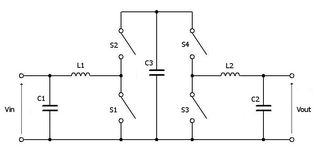
In electronics, a split-pi topology is a pattern of component interconnections used in a kind of power converter that can theoretically produce an arbitrary output voltage, either higher or lower than the input voltage. In practice the upper voltage output is limited to the voltage rating of components used. It is essentially a boost (step-up) converter followed by a buck (step-down) converter. The topology and use of MOSFETs make it inherently bi-directional which lends itself to applications requiring regenerative braking.
Within the electronics industry, a Multi-port Power Electronic Interface (MPEI) is a self-sustainable multiple input/output static power electronic converter. It is capable of interfacing with different sources, storages, and loads. The integrated control system of MPEI enables excellent dynamic and steady state performance, which renders optimal renewable energy harvesting, optimal energy management, and optimal and economical utility grid interactions in a deregulated power market.

Frede Blaabjerg is a Danish professor at Aalborg University. At Aalborg, he works in the section of Power Electronic Systems of the department of Energy Technology. Blaabjerg's research concerns the applications of power electronics, including adjustable-speed drives, microgrids, photovoltaic systems, and wind turbines. By the number of citations, he is the most cited author of several IEEE journals: IEEE Transactions on Power Electronics, IEEE Transactions on Industry Applications, IEEE Journal of Emerging and Selected Topics in Power Electronics.

Synchronverters or virtual synchronous generators are inverters which mimic synchronous generators (SG) to provide "synthetic inertia" for ancillary services in electric power systems. Inertia is a property of standard synchronous generators associated with the rotating physical mass of the system spinning at a frequency proportional to the electricity being generated. Inertia has implications towards grid stability as work is required to alter the kinetic energy of the spinning physical mass and therefore opposes changes in grid frequency. Inverter-based generation inherently lacks this property as the waveform is being created artificially via power electronics.

NL5 is a mixed-signal electronic circuit simulator with ideal and piecewise-linear components.
A multi-level converter (MLC) or is a method of generating high-voltage wave-forms from lower-voltage components. MLC origins go back over a hundred years, when in the 1880s, the advantages of DC long-distance transmission became evident.
The black box model of power converter also called behavior model, is a method of system identification to represent the characteristics of power converter, that is regarded as a black box. There are two types of black box model of power converter - when the model includes the load, it is called terminated model, otherwise un-terminated model. The type of black box model of power converter is chosen based on the goal of modeling. This black box model of power converter could be a tool for filter design of a system integrated with power converters.
Switching Control Techniques address electromagnetic interference (EMI) mitigation on power electronics (PE). The design of power electronics involves overcoming three key challenges:
- power losses
- EMI
- harmonics

Fang Zheng Peng is the Director, Energy GRID Institute and a RK Mellon Endowed Chair Professor of Electrical and Computer Engineering in the University of Pittsburgh, U.S. Earlier, he was a Distinguished Professor of Engineering at the Center for Advanced Power Systems, Florida State University, U.S. His primary research area is power electronics, covering the development of Z-source inverters and multievel inverters for STATCOM applications to improve power flow capability.
References
- ↑ Siwakoti, Yam P.; Peng, Fang Zheng; Blaabjerg, Frede; Loh, Poh Chiang; Town, Graham E. (2015). "Impedance-Source Networks for Electric Power Conversion Part I: A Topological Review". IEEE Transactions on Power Electronics . 30 (2): 699–716. Bibcode:2015ITPE...30..699S. doi: 10.1109/TPEL.2014.2313746 . S2CID 44236767.
- ↑ Siwakoti, Yam P.; Peng, Fang Zheng; Blaabjerg, Frede; Loh, Poh Chiang; Town, Graham E.; Yang, Shuitao (2015). "Impedance-Source Networks for Electric Power Conversion Part II: Review of Control and Modulation Techniques". IEEE Transactions on Power Electronics . 30 (4): 1887–1906. Bibcode:2015ITPE...30.1887S. doi: 10.1109/TPEL.2014.2329859 . S2CID 39497030.
- 1 2 Siwakoti, Yam P.; Blaabjerg, Frede; Loh, Poh Chiang (2016). "New Magnetically Coupled Impedance (Z-) Source Networks". IEEE Transactions on Power Electronics . 31 (11): 7419–7435. Bibcode:2016ITPE...31.7419S. doi:10.1109/TPEL.2015.2459233. S2CID 21489048.
- ↑ Adamowicz, Marek (2011). "LCCT-Z-Source inverters". 2011 10th International Conference on Environment and Electrical Engineering. pp. 1–6. doi:10.1109/EEEIC.2011.5874799. ISBN 978-1-4244-8779-0. S2CID 27917468.
- ↑ Siwakoti, Yam P.; Loh, Poh Chiang; Blaabjerg, Frede; Town, Graham (2014). "Y-source impedance network". 2014 IEEE Applied Power Electronics Conference and Exposition - APEC 2014. pp. 3362–3366. doi:10.1109/APEC.2014.6803789. ISBN 978-1-4799-2325-0. S2CID 21361731.
- ↑ Rashid, M. (2011) Power Electronics. Pearson Education. ISBN 8131762297
- 1 2 Shen, Miaosen; Peng, Fang Zheng (2008). "Operation Modes and Characteristics of the Z-Source Inverter with Small Inductance or Low Power Factor". IEEE Transactions on Industrial Electronics. 55: 89–96. doi:10.1109/TIE.2007.909063. S2CID 10619253.
- ↑ Florescu, A.; Stocklosa, O.; Teodorescu, M.; Radoi, C.; Stoichescu, D. A.; Rosu, S. (2010). "The advantages, limitations and disadvantages of Z-source inverter". CAS 2010 Proceedings (International Semiconductor Conference). pp. 483–486. doi:10.1109/SMICND.2010.5650503. ISBN 978-1-4244-5782-3. S2CID 33649768.
- ↑ Murali, M.; Gopalakrishnan, N.; Pande, V.N. (2012). "Z-sourced unified power flow controller". 6th IET International Conference on Power Electronics, Machines and Drives (PEMD 2012). pp. A74. doi:10.1049/cp.2012.0222. ISBN 978-1-84919-616-1.
- ↑ Fang Zheng Peng (2003). "Z-source inverter". IEEE Transactions on Industry Applications. 39 (2): 504–510. doi:10.1109/TIA.2003.808920.
- ↑ Shen, M.; Joseph, A.; Wang, J.; Peng, F.Z.; Adams, D.J. (2004). "Comparison of traditional inverters and Z-source inverter for fuel cell vehicles". Power Electronics in Transportation (IEEE Cat. No.04TH8756). pp. 125–132. doi:10.1109/PET.2004.1393815. ISBN 0-7803-8538-1. S2CID 5782046.