In electronics, the figures of merit of an amplifier are numerical measures that characterize its properties and performance. Figures of merit can be given as a list of specifications that include properties such as gain, bandwidth, noise and linearity, among others listed in this article. Figures of merit are important for determining the suitability of a particular amplifier for an intended use.

An amplifier, electronic amplifier or (informally) amp is an electronic device that can increase the magnitude of a signal. It is a two-port electronic circuit that uses electric power from a power supply to increase the amplitude of a signal applied to its input terminals, producing a proportionally greater amplitude signal at its output. The amount of amplification provided by an amplifier is measured by its gain: the ratio of output voltage, current, or power to input. An amplifier is defined as a circuit that has a power gain greater than one.

An operational amplifier is a DC-coupled electronic voltage amplifier with a differential input, a (usually) single-ended output, and an extremely high gain. Its name comes from its original use of performing mathematical operations in analog computers.

In electronics, an analog-to-digital converter is a system that converts an analog signal, such as a sound picked up by a microphone or light entering a digital camera, into a digital signal. An ADC may also provide an isolated measurement such as an electronic device that converts an analog input voltage or current to a digital number representing the magnitude of the voltage or current. Typically the digital output is a two's complement binary number that is proportional to the input, but there are other possibilities.
Capacitive coupling is the transfer of energy within an electrical network or between distant networks by means of displacement current between circuit(s) nodes, induced by the electric field. This coupling can have an intentional or accidental effect.

Pulse-width modulation (PWM), also known as pulse-duration modulation (PDM) or pulse-length modulation (PLM), is any method of representing a signal as a rectangular wave with a varying duty cycle.
This is an index of articles relating to electronics and electricity or natural electricity and things that run on electricity and things that use or conduct electricity.

A voltage-controlled oscillator (VCO) is an electronic oscillator whose oscillation frequency is controlled by a voltage input. The applied input voltage determines the instantaneous oscillation frequency. Consequently, a VCO can be used for frequency modulation (FM) or phase modulation (PM) by applying a modulating signal to the control input. A VCO is also an integral part of a phase-locked loop. VCOs are used in synthesizers to generate a waveform whose pitch can be adjusted by a voltage determined by a musical keyboard or other input.

Power electronics is the application of electronics to the control and conversion of electric power.
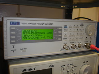
Direct digital synthesis (DDS) is a method employed by frequency synthesizers used for creating arbitrary waveforms from a single, fixed-frequency reference clock. DDS is used in applications such as signal generation, local oscillators in communication systems, function generators, mixers, modulators, sound synthesizers and as part of a digital phase-locked loop.

In electronics, a chopper circuit is any of numerous types of electronic switching devices and circuits used in power control and signal applications. A chopper is a device that converts fixed DC input to a variable DC output voltage directly. Essentially, a chopper is an electronic switch that is used to interrupt one signal under the control of another.
This article illustrates some typical operational amplifier applications. A non-ideal operational amplifier's equivalent circuit has a finite input impedance, a non-zero output impedance, and a finite gain. A real op-amp has a number of non-ideal features as shown in the diagram, but here a simplified schematic notation is used, many details such as device selection and power supply connections are not shown. Operational amplifiers are optimised for use with negative feedback, and this article discusses only negative-feedback applications. When positive feedback is required, a comparator is usually more appropriate. See Comparator applications for further information.
A radio transmitter or just transmitter is an electronic device which produces radio waves with an antenna. Radio waves are electromagnetic waves with frequencies between about 30 Hz and 300 GHz. The transmitter itself generates a radio frequency alternating current, which is applied to the antenna. When excited by this alternating current, the antenna radiates radio waves. Transmitters are necessary parts of all systems that use radio: radio and television broadcasting, cell phones, wireless networks, radar, two way radios like walkie talkies, radio navigation systems like GPS, remote entry systems, among numerous other uses.
In electronics and signal processing, signal conditioning is the manipulation of an analog signal in such a way that it meets the requirements of the next stage for further processing.
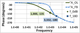
In electronic amplifiers, the phase margin (PM) is the difference between the phase lag φ and -180°, for an amplifier's output signal at zero dB gain - i.e. unity gain, or that the output signal has the same amplitude as the input.

An oscilloscope is a type of electronic test instrument that graphically displays varying voltages of one or more signals as a function of time. Their main purpose is capturing information on electrical signals for debugging, analysis, or characterization. The displayed waveform can then be analyzed for properties such as amplitude, frequency, rise time, time interval, distortion, and others. Originally, calculation of these values required manually measuring the waveform against the scales built into the screen of the instrument. Modern digital instruments may calculate and display these properties directly.

A digital signal is a signal that represents data as a sequence of discrete values; at any given time it can only take on, at most, one of a finite number of values. This contrasts with an analog signal, which represents continuous values; at any given time it represents a real number within a continuous range of values.
A comparator is an electronic component that compares two input voltages. Comparators are closely related to operational amplifiers, but a comparator is designed to operate with positive feedback and with its output saturated at one power rail or the other. If necessary, an op-amp can be pressed into service as a poorly performing comparator, but its slew Rate will be impaired.
This glossary of electrical and electronics engineering is a list of definitions of terms and concepts related specifically to electrical engineering and electronics engineering. For terms related to engineering in general, see Glossary of engineering.
In electronics, power amplifier classes are letter symbols applied to different power amplifier types. The class gives a broad indication of an amplifier's characteristics and performance. The first three classes are related to the time period that the active amplifier device is passing current, expressed as a fraction of the period of a signal waveform applied to the input. This metric is known as conduction angle (θ). A class A amplifier is conducting through all the period of the signal (θ=360°); Class B only for one-half the input period (θ=180°), class C for much less than half the input period (θ<180°). Class D amplifiers operate their output device in a switching manner; the fraction of the time that the device is conducting may be adjusted so a pulse-width modulation output can be obtained from the stage.
