Delamination

Last updated
Delamination of carbon fiber-reinforced polymer under compression load Delamination-CFRP.jpg
Delamination of carbon fiber–reinforced polymer under compression load

Delamination is a mode of failure where a material fractures into layers. A variety of materials, including laminate composites [1] and concrete, can fail by delamination. Processing can create layers in materials, such as steel formed by rolling [2] [3] and plastics and metals from 3D printing [4] [5] which can fail from layer separation. Also, surface coatings, such as paints and films, can delaminate from the coated substrate.

Contents

In laminated composites, the adhesion between layers often fails first, causing the layers to separate. [6] For example, in fiber-reinforced plastics, sheets of high strength reinforcement (e.g., carbon fiber, fiberglass) are bound together by a much weaker polymer matrix (e.g., epoxy). In particular, loads applied perpendicular to the high strength layers, and shear loads can cause the polymer matrix to fracture or the fiber reinforcement to debond from the polymer.

Delamination also occurs in reinforced concrete when metal reinforcements near the surface corrode. [7] The oxidized metal has a larger volume causing stresses when confined by the concrete. When the stresses exceed the strength of the concrete, cracks can form and spread to join with neighboring cracks caused by corroded rebar creating a fracture plane that runs parallel to the surface. Once the fracture plane has developed, the concrete at the surface can separate from the substrate.

Processing can create layers in materials which can fail by delamination. In concrete, surfaces can flake off from improper finishing. If the surface is finished and densified by troweling while the underlying concrete is bleeding water and air, the dense top layer may separate from the water and air pushing upwards. [8] In steels, rolling can create a microstructure when the microscopic grains are oriented in flat sheets which can fracture into layers. [2] Also, certain 3D printing methods (e.g., Fused Deposition) builds parts in layers that can delaminate during printing or use. When printing thermoplastics with fused deposition, cooling a hot layer of plastic applied to a cold substrate layer can cause bending due to differential thermal contraction and layer separation. [4]

Inspection methods

There are multiple nondestructive testing methods to detect delamination in structures including visual inspection, tap testing (i.e. sounding), ultrasound, radiography, and infrared imaging.

Visual inspection is useful for detecting delaminations at the surface and edges of materials. However, a visual inspection may not detect delamination within a material without cutting the material open.

Tap testing or sounding involves gently striking the material with a hammer or hard object to find delamination based on the resulting sound. In laminated composites, a clear ringing sound indicates a well bonded material whereas a duller sound indicates the presence of delamination due to the defect dampening the impact. [9] Tap testing is well suited for finding large defects in flat panel composites with a honeycomb core whereas thin laminates may have small defects that are not discernible by sound. [10] Using sound is also subjective and dependent on the inspector's quality of hearing as well as judgement. Any intentional variations in the part may also change the pitch of the produced sound, influencing the inspection. Some of these variations include ply overlaps, ply count change gores, core density change (if used), and geometry.

In reinforced concretes intact regions will sound solid whereas delaminated areas will sound hollow. [11] Tap testing large concrete structures is carried about either with a hammer or with a chain dragging device for horizontal surfaces like bridge decks. Bridge decks in cold climate countries which use de-icing salts and chemicals are commonly subject to delamination and as such are typically scheduled for annual inspection by chain-dragging as well as subsequent patch repairs of the surface. [12]

Delamination resistance testing methods

Coating delamination tests

ASTM provides standards for paint adhesion testing which provides qualitative measures for paints and coatings resistance to delamination from substrates. Tests include cross-cut test, scrape adhesion, [13] and pull-off test. [14]

Interlaminar fracture toughness testing

Fracture toughness is a material property that describes resistance to fracture and delamination. It is denoted by critical stress intensity factor or critical strain energy release rate . [15] For unidirectional fiber reinforced polymer laminate composites, ASTM provides standards for determining mode I fracture toughness and mode II fracture toughness of the interlaminar matrix. [16] [17] During the tests load and displacement is recorded for analysis to determine the strain energy release rate from the compliance method. in terms of compliance is given by

(1)

where is the change in compliance (ratio of ), is the thickness of the specimen, and is the change in crack length.

Mode I interlaminar fracture toughness

Schematic of deformed double cantilever beam specimen. Double Cantilever Beam Specimen Deformed Schematic.svg
Schematic of deformed double cantilever beam specimen.

ASTM D5528 specifies the use of the double cantilever beam (DCB) specimen geometry for determining mode I interlaminar fracture toughness. [17] A double cantilever beam specimen is created by placing a non-stick film between reinforcement layers in the center of the beam before curing the polymer matrix to create an initial crack of length . During the test the specimen is loaded in tension from the end of the initial crack side of the beam opening the crack. Using the compliance method, the critical strain energy release rate is given by

(2)

where and are the maximum load and displacement respectively by determining when the load deflection curve has become nonlinear with a line drawn from the origin with a 5% increase in compliance. Typically, equation 2 overestimates the fracture toughness because the two cantilever beams of the DCB specimen will have a finite rotation at the crack. The finite rotation can be corrected for by calculating with a slightly longer crack with length giving

(3)

The crack length correction can be calculated experimentally by plotting the least squares fit of the cube root of the compliance vs. crack length . The correction is the absolute value of the x intercept. Fracture toughness can also be corrected with the compliance calibration method where given by

(4)

where is the slope of the least squares fit of vs. .

Mode II interlaminar fracture toughness

Schematic of edge notch flexure test. Edge Notch Flexure Schematic Test PNG.png
Schematic of edge notch flexure test.

Mode II interlaminar fracture toughness can be determined by an edge notch flexure test specified by ASTM D7905. [16] The specimen is prepared in a similar manner as the DCB specimen introducing an initial crack with length before curing the polymer matrix. If the test is performed with the initial crack (non-precracked method) the candidate fracture toughness is given by

where is the thickness of the specimen and is the max load and is a fitting parameter. is determined by experimental results with a least squares fit of compliance vs. the crack length cubed with the form of

.

The candidate fracture toughness equals the mode II fracture toughness if strain energy release rate falls within certain percentage of at different crack lengths specified by ASTM.

Interlaminar shear strength testing

Interlaminar shear strength is used as an additional measure of the strength of the fiber-matrix bond in fiber-reinforced composites. Shear-induced delamination is experienced in various loading conditions where the bending moment across the composite changes rapidly, such as in pipes with changes in thickness or bends. [18] Multiple test architectures have been proposed for use in measuring interlaminar shear strength, including the short beam shear test, Iosipescu test, rail shear test, and asymmetrical four-point bending test. [19] The goal of each of these tests is to maximize the ratio of shear stress to tensile stress exhibited in the sample, promoting failure via delamination of the fiber-matrix interface instead of through fiber tension or buckling. [20] The orthotropic symmetry of fiber composite materials makes a state of pure shear stress difficult to obtain in sample testing; thin cylindrical specimens can be used but are costly to manufacture. [21] Sample geometries are thus chosen for ease of machining and optimization of the stress state when loaded.

In addition to manufactured composites such as glass fiber-reinforced polymers, interlaminar shear strength is an important property in natural materials such as wood. The long, thin shape of floorboards, for example, may promote deformation that leads to vibrations. [22]

Asymmetric four-point bending

(top-bottom) The point forces, shear stresses, and moments acting on an asymmetric four point bend test sample Asymmetric Four Point Bend Force-Shear-Moment Diagram.jpg
(top-bottom) The point forces, shear stresses, and moments acting on an asymmetric four point bend test sample

Asymmetric four-point bending (AFPB) may be chosen to measure interlaminar shear strength over other procedures for a variety of reasons, including specimen machinability, test reproducibility, and equipment availability. For example, short-beam shear samples are constrained to a specific length-thickness ratio to prevent bending failure, and the shear stress distribution across the specimen is non-uniform, both of which contribute to a lack of reproducibility. [19] Rail shear testing also produces a non-homogeneous shear stress state, making it appropriate for determining shear modulus, but not shear strength. [19] The Iosipescu test requires special equipment in addition to the roller setup already used for other three- and four-point flexural tests. [22]

ASTM C1469 outlines a standard for AFPB testing of advanced ceramic joints, and the method has been proposed to be adapted for use with continuous ceramic matrix composites. [23] [24] Rectangular samples can be used with or without notches machined at the center; the addition of notches helps to control the position of the failure along the length of the sample, but improper or nonsymmetrical machining can result in the addition of undesired normal stresses which reduce the measured strength. [24] The sample is then loaded in compression in its test fixture, with loading applied directly to the sample from 4 loading pins arranged in a parallelogram-like configuration. The load applied from the test fixture is transferred unevenly to the top two pins; the ratio of the inner pin load and outer pin load is defined as the loading factor , such that

,

where and are the lengths from the inner pin to the applied point load and from the outer pin to the applied point load, respectively. The normal stress in the sample is maximized at the locations of the inner pins, and is equivalent to

,

where is the total applied load on the sample, is the sample length, is the sample width (into the page as seen in a 2D free-body diagram), and is the sample thickness. The shear stress in the sample is maximized in between the inner span of the pins and is given by

.

The ratio of normal to shear stress in the sample is given by

.

This ratio is dependent both on the loading factor of the sample and its length-thickness ratio; both of these quantities are important in determining the mode of failure of the sample in testing. [18]

Related Research Articles

<span class="mw-page-title-main">Composite material</span> Material made from a combination of two or more unlike substances

A composite material is a material which is produced from two or more constituent materials. These constituent materials have notably dissimilar chemical or physical properties and are merged to create a material with properties unlike the individual elements. Within the finished structure, the individual elements remain separate and distinct, distinguishing composites from mixtures and solid solutions. Composite materials with more than one distinct layer are called composite laminates.

<span class="mw-page-title-main">Fracture</span> Split of materials or structures under stress

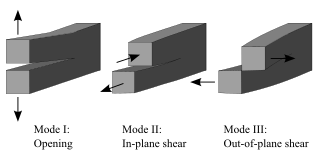
Fracture is the appearance of a crack or complete separation of an object or material into two or more pieces under the action of stress. The fracture of a solid usually occurs due to the development of certain displacement discontinuity surfaces within the solid. If a displacement develops perpendicular to the surface, it is called a normal tensile crack or simply a crack; if a displacement develops tangentially, it is called a shear crack, slip band, or dislocation.

<span class="mw-page-title-main">Compressive strength</span> Capacity of a material or structure to withstand loads tending to reduce size

In mechanics, compressive strength is the capacity of a material or structure to withstand loads tending to reduce size. In other words, compressive strength resists compression, whereas tensile strength resists tension. In the study of strength of materials, tensile strength, compressive strength, and shear strength can be analyzed independently.

<span class="mw-page-title-main">Fatigue (material)</span> Initiation and propagation of cracks in a material due to cyclic loading

In materials science, fatigue is the initiation and propagation of cracks in a material due to cyclic loading. Once a fatigue crack has initiated, it grows a small amount with each loading cycle, typically producing striations on some parts of the fracture surface. The crack will continue to grow until it reaches a critical size, which occurs when the stress intensity factor of the crack exceeds the fracture toughness of the material, producing rapid propagation and typically complete fracture of the structure.

<span class="mw-page-title-main">Fracture mechanics</span> Study of propagation of cracks in materials

Fracture mechanics is the field of mechanics concerned with the study of the propagation of cracks in materials. It uses methods of analytical solid mechanics to calculate the driving force on a crack and those of experimental solid mechanics to characterize the material's resistance to fracture.

<span class="mw-page-title-main">Fracture toughness</span> Stress intensity factor at which a cracks propagation increases drastically

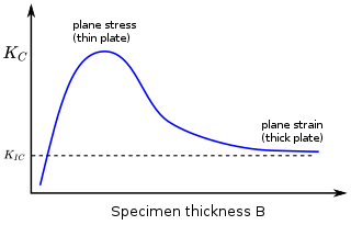
In materials science, fracture toughness is the critical stress intensity factor of a sharp crack where propagation of the crack suddenly becomes rapid and unlimited. A component's thickness affects the constraint conditions at the tip of a crack with thin components having plane stress conditions and thick components having plane strain conditions. Plane strain conditions give the lowest fracture toughness value which is a material property. The critical value of stress intensity factor in mode I loading measured under plane strain conditions is known as the plane strain fracture toughness, denoted . When a test fails to meet the thickness and other test requirements that are in place to ensure plane strain conditions, the fracture toughness value produced is given the designation . Fracture toughness is a quantitative way of expressing a material's resistance to crack propagation and standard values for a given material are generally available.

<span class="mw-page-title-main">Three-point flexural test</span> Standard procedure for measuring modulus of elasticity in bending

The three-point bending flexural test provides values for the modulus of elasticity in bending , flexural stress , flexural strain and the flexural stress–strain response of the material. This test is performed on a universal testing machine with a three-point or four-point bend fixture. The main advantage of a three-point flexural test is the ease of the specimen preparation and testing. However, this method has also some disadvantages: the results of the testing method are sensitive to specimen and loading geometry and strain rate.

Methods have been devised to modify the yield strength, ductility, and toughness of both crystalline and amorphous materials. These strengthening mechanisms give engineers the ability to tailor the mechanical properties of materials to suit a variety of different applications. For example, the favorable properties of steel result from interstitial incorporation of carbon into the iron lattice. Brass, a binary alloy of copper and zinc, has superior mechanical properties compared to its constituent metals due to solution strengthening. Work hardening has also been used for centuries by blacksmiths to introduce dislocations into materials, increasing their yield strengths.

Rubber toughening is a process in which rubber nanoparticles are interspersed within a polymer matrix to increase the mechanical robustness, or toughness, of the material. By "toughening" a polymer it is meant that the ability of the polymeric substance to absorb energy and plastically deform without fracture is increased. Considering the significant advantages in mechanical properties that rubber toughening offers, most major thermoplastics are available in rubber-toughened versions; for many engineering applications, material toughness is a deciding factor in final material selection.

<span class="mw-page-title-main">Fiber-reinforced composite</span>

A fiber-reinforced composite (FRC) is a composite building material that consists of three components:

  1. the fibers as the discontinuous or dispersed phase,
  2. the matrix as the continuous phase, and
  3. the fine interphase region, also known as the interface.
<span class="mw-page-title-main">Ceramic matrix composite</span> Composite material consisting of ceramic fibers in a ceramic matrix

In materials science ceramic matrix composites (CMCs) are a subgroup of composite materials and a subgroup of ceramics. They consist of ceramic fibers embedded in a ceramic matrix. The fibers and the matrix both can consist of any ceramic material, including carbon and carbon fibers.

Carbon fiber-reinforced polymers, carbon-fibre-reinforced polymers, carbon-fiber-reinforced plastics, carbon-fiber reinforced-thermoplastic, also known as carbon fiber, carbon composite, or just carbon, are extremely strong and light fiber-reinforced plastics that contain carbon fibers. CFRPs can be expensive to produce, but are commonly used wherever high strength-to-weight ratio and stiffness (rigidity) are required, such as aerospace, superstructures of ships, automotive, civil engineering, sports equipment, and an increasing number of consumer and technical applications.

<span class="mw-page-title-main">Tensile testing</span> Test procedure to determine mechanical properties of a specimen.

Tensile testing, also known as tension testing, is a fundamental materials science and engineering test in which a sample is subjected to a controlled tension until failure. Properties that are directly measured via a tensile test are ultimate tensile strength, breaking strength, maximum elongation and reduction in area. From these measurements the following properties can also be determined: Young's modulus, Poisson's ratio, yield strength, and strain-hardening characteristics. Uniaxial tensile testing is the most commonly used for obtaining the mechanical characteristics of isotropic materials. Some materials use biaxial tensile testing. The main difference between these testing machines being how load is applied on the materials.

The wafer bond characterization is based on different methods and tests. Considered a high importance of the wafer are the successful bonded wafers without flaws. Those flaws can be caused by void formation in the interface due to unevenness or impurities. The bond connection is characterized for wafer bond development or quality assessment of fabricated wafers and sensors.

Polymer fracture is the study of the fracture surface of an already failed material to determine the method of crack formation and extension in polymers both fiber reinforced and otherwise. Failure in polymer components can occur at relatively low stress levels, far below the tensile strength because of four major reasons: long term stress or creep rupture, cyclic stresses or fatigue, the presence of structural flaws and stress-cracking agents. Formations of submicroscopic cracks in polymers under load have been studied by x ray scattering techniques and the main regularities of crack formation under different loading conditions have been analyzed. The low strength of polymers compared to theoretically predicted values are mainly due to the many microscopic imperfections found in the material. These defects namely dislocations, crystalline boundaries, amorphous interlayers and block structure can all lead to the non-uniform distribution of mechanical stress.

<span class="mw-page-title-main">Crack tip opening displacement</span>

Crack tip opening displacement (CTOD) or is the distance between the opposite faces of a crack tip at the 90° intercept position. The position behind the crack tip at which the distance is measured is arbitrary but commonly used is the point where two 45° lines, starting at the crack tip, intersect the crack faces. The parameter is used in fracture mechanics to characterize the loading on a crack and can be related to other crack tip loading parameters such as the stress intensity factor and the elastic-plastic J-integral.

The four-point flexural test provides values for the modulus of elasticity in bending , flexural stress , flexural strain and the flexural stress-strain response of the material. This test is very similar to the three-point bending flexural test. The major difference being that with the addition of a fourth bearing the portion of the beam between the two loading points is put under maximum stress, as opposed to only the material right under the central bearing in the case of three-point bending.

In materials science, toughening refers to the process of making a material more resistant to the propagation of cracks. When a crack propagates, the associated irreversible work in different materials classes is different. Thus, the most effective toughening mechanisms differ among different materials classes. The crack tip plasticity is important in toughening of metals and long-chain polymers. Ceramics have limited crack tip plasticity and primarily rely on different toughening mechanisms.

Welding of advanced thermoplastic composites is a beneficial method of joining these materials compared to mechanical fastening and adhesive bonding. Mechanical fastening requires intense labor, and creates stress concentrations, while adhesive bonding requires extensive surface preparation, and long curing cycles. Welding these materials is a cost-effective method of joining concerning preparation and execution, and these materials retain their properties upon cooling, so no post processing is necessary. These materials are widely used in the aerospace industry to reduce weight of a part while keeping strength.

Implant resistance welding is a method used in welding to join thermoplastics and thermoplastic composites.

References

  1. Cantwell, W.J.; Morton, J. (1991). "The impact resistance of composite materials — a review". Composites. 22 (5): 347–362. doi:10.1016/0010-4361(91)90549-V.
  2. 1 2 Bramfitt, B. L.; Marder, A. R. (1977). "A study of the delamination behavior of a very low-carbon steel". Metallurgical Transactions A. 8 (8): 1263–1273. Bibcode:1977MTA.....8.1263B. doi:10.1007/bf02643841. ISSN   0360-2133. S2CID   136949441.
  3. Dogan, Mizam (2011). "Delamination failure of steel single angle sections". Engineering Failure Analysis. 18 (7): 1800–1807. doi:10.1016/j.engfailanal.2011.04.009.
  4. 1 2 "Layer Separation and Splitting". Prusa3D - 3D Printers from Josef Průša. 2019-01-04. Retrieved 2019-05-03.
  5. Barile, Claudia; Casavola, Caterina; Cazzato, Alberto (2018-09-18). "Acoustic Emissions in 3D Printed Parts under Mode I Delamination Test". Materials. 11 (9): 1760. Bibcode:2018Mate...11.1760B. doi: 10.3390/ma11091760 . ISSN   1996-1944. PMC   6165299 . PMID   30231488.
  6. Wisnom, M. R. (2012-04-28). "The role of delamination in failure of fibre-reinforced composites". Philosophical Transactions of the Royal Society A: Mathematical, Physical and Engineering Sciences. 370 (1965): 1850–1870. Bibcode:2012RSPTA.370.1850W. doi: 10.1098/rsta.2011.0441 . ISSN   1364-503X. PMID   22431760.
  7. Li, C. Q.; Zheng, J. J.; Lawanwisut, W.; Melchers, R. E. (2007). "Concrete Delamination Caused by Steel Reinforcement Corrosion". Journal of Materials in Civil Engineering. 19 (7): 591–600. doi:10.1061/(ASCE)0899-1561(2007)19:7(591). ISSN   0899-1561.
  8. "CIP 20 - Delamination of Troweled Concrete Surfaces" (PDF). NRMCA National Ready Mix Concrete Association. May 4, 2019. Archived from the original (PDF) on July 28, 2019. Retrieved May 15, 2019.
  9. "DOT/FAA/AR-02/121: Guidelines for Analysis, Testing, and Nondestructive Inspection of Impact- Damaged Composite Sandwich Structures" (PDF). March 2003.
  10. "The Limitations of Tap Testing". carbonbikerepair.com.au. Retrieved 2019-05-16.
  11. ASTM ASTM D4580/D4580M - 12: Standard Practice for Measuring Delaminations in Concrete Bridge Decks by Sounding, West Conshohocken, PA: ASTM International, 2018
  12. Ahmadi, Hossein (December 2017). Concrete Bridge Deck Aging, Inspection and Maintenance (Master of Science thesis). University of Toledo. Archived from the original on 2019-05-16. Retrieved 2019-05-16.
  13. ASTM D2197 - 98: Standard Test Method for Adhesion of Organic Coatings by Scrape Adhesion, West Conshohocken, PA: ASTM International, 1998
  14. ASTM D4541 - 17: Standard Test Method for Pull-Off Strength of Coatings Using Portable Adhesion Testers, West Conshohocken, PA: ASTM International, 2017
  15. Zehnder, Alan (2012). Fracture mechanics. Springer. ISBN   9789400725959. OCLC   905283457.
  16. 1 2 ASTM D7905/D7905M - 14: Standard Test Method for Determination of the Mode II Interlaminar Fracture Toughness of Unidirectional Fiber-Reinforced Polymer Matrix Composites, West Conshohocken, PA: ASTM International, 2014
  17. 1 2 ASTM D5528 - 13: Standard Test Method for Mode I Interlaminar Fracture Toughness of Unidirectional Fiber-Reinforced Polymer Matrix Composites, West Conshohocken, PA: ASTM International, 2014
  18. 1 2 Theotokoglou, E.E.; Sideridis, E. (July 2011). "Study of composite beams in asymmetric four-point bending". Journal of Reinforced Plastics and Composites. 30 (13): 1125–1137. doi:10.1177/0731684411417199.
  19. 1 2 3 Spigel, Barry Stuart. An Experimental and Analytical Investigation of the Iosipescu Shear Test for Composite Materials (Thesis). doi:10.25777/1f0a-4934.
  20. Spigel, B. S.; Prabhakaran, R.; Sawyer, J. W. (March 1987). "An investigation of the losipescu and asymmetrical four-point bend tests". Experimental Mechanics. 27 (1): 57–63. doi:10.1007/BF02318864.
  21. Prabhakaran, R.; Sawyer, Wayne (January 1986). "A photoelastic investigation of asymmetric four point bend shear test for composite materials". Composite Structures. 5 (3): 217–231. doi:10.1016/0263-8223(86)90004-8.
  22. 1 2 Yoshihara, Hiroshi; Kubojima, Yoshitaka (February 2002). "Measurement of the shear modulus of wood by asymmetric four-point bending tests". Journal of Wood Science. 48 (1): 14–19. doi:10.1007/BF00766232.
  23. Jadhav, Prakash; Lande, Chhaya (27 July 2023). "Asymmetric Four Point Bend Test Method for Interlaminar Shear Strength in Ceramic Matrix Composites". Materials Science Forum. 1094: 19–24. doi:10.4028/p-zN31vp.
  24. 1 2 ASTM C1469 - 10: Standard Test Method for Shear Strength of Joints of Advanced Ceramics at Ambient Temperature, West Conshohocken, PA: ASTM International, 2015