Components of an electrical circuit are electrically connected if an electric current can run between them through an electrical conductor. An electrical connector is an electromechanical device used to create an electrical connection between parts of an electrical circuit, or between different electrical circuits, thereby joining them into a larger circuit.

IEC 60320 Appliance couplers for household and similar general purposes is a set of standards from the International Electrotechnical Commission (IEC) specifying non-locking connectors for connecting power supply cords to electrical appliances of voltage not exceeding 250 V (a.c.) and rated current not exceeding 16 A. Different types of connector are specified for different combinations of current, temperature and earthing requirements. Unlike IEC 60309 connectors, they are not coded for voltage; users must ensure that the voltage rating of the equipment is compatible with the mains supply. The standard uses the term coupler to encompass connectors on power cords and power inlets and outlets built into appliances.
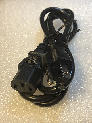
A power cord, line cord, or mains cable is an electrical cable that temporarily connects an appliance to the mains electricity supply via a wall socket or extension cord. The terms are generally used for cables using a power plug to connect to a single-phase alternating current power source at the local line voltage. The terms power cable, mains lead, flex or kettle lead are also used. A lamp cord is a light-weight, ungrounded, single-insulated two-wire cord used for small loads such as a table or floor lamp.

A residual-current device (RCD), residual-current circuit breaker (RCCB) or ground fault circuit interrupter (GFCI) is an electrical safety device that quickly breaks an electrical circuit with leakage current to ground. It is to protect equipment and to reduce the risk of serious harm from an ongoing electric shock. Injury may still occur in some cases, for example if a human receives a brief shock before the electrical circuit is isolated, falls after receiving a shock, or if the person touches both conductors at the same time.
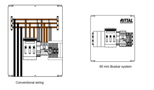
A distribution board is a component of an electricity supply system that divides an electrical power feed into subsidiary circuits while providing a protective fuse or circuit breaker for each circuit in a common enclosure. Normally, a main switch, and in recent boards, one or more residual-current devices (RCDs) or residual current breakers with overcurrent protection (RCBOs) are also incorporated.

AC power plugs and sockets connect devices to mains electricity to supply them with electrical power. A plug is the connector attached to an electrically-operated device, often via a cable. A socket is fixed in place, often on the internal walls of buildings, and is connected to an AC electrical circuit. Inserting the plug into the socket allows the device to draw power from this circuit.

A telephone jack and a telephone plug are electrical connectors for connecting a telephone set or other telecommunications apparatus to the telephone wiring inside a building, establishing a connection to a telephone network. The plug is inserted into its counterpart, the jack, which is commonly affixed to a wall or baseboard. The standards for telephone jacks and plugs vary from country to country, though the 6P2C style modular plug has become by far the most common type.

IEC 60309 is a series of international standards from the International Electrotechnical Commission (IEC) for "plugs, socket-outlets and couplers for industrial purposes". They are also referred to as "pin & sleeve" connectors in North America or as "CeeForm" connectors in the entertainment industry. The maximum voltage allowed by the standard is 1000 V DC or AC; the maximum current, 800 A; and the maximum frequency, 500 Hz. The ambient temperature range is −25 °C to 40 °C.
In electricity supply design, a ring circuit is an electrical wiring technique in which sockets and the distribution point are connected in a ring. It is contrasted with the usual radial circuit, in which sockets and the distribution point are connected in a line with the distribution point at one end.
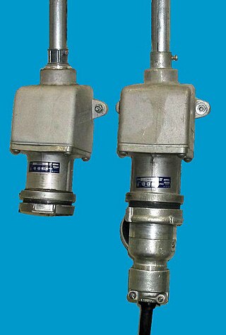
Industrial and multiphase plugs and sockets provide a connection to the electrical mains rated at higher voltages and currents than household plugs and sockets. They are generally used in polyphase systems, with high currents, or when protection from environmental hazards is required. Industrial outlets may have weatherproof covers, waterproofing sleeves, or may be interlocked with a switch to prevent accidental disconnection of an energized plug. Some types of connectors are approved for hazardous areas such as coal mines or petrochemical plants, where flammable gas may be present.

In electrical and mechanical trades and manufacturing, each half of a pair of mating connectors or fasteners is conventionally assigned the designation male or female. The female connector is generally a receptacle that receives and holds the male connector. Alternative terminology such as plug and socket or jack are sometimes used, particularly for electrical connectors.

In electrical engineering, ground and neutral are circuit conductors used in alternating current (AC) electrical systems. The ground circuit is connected to earth, and neutral circuit is usually connected to ground. As the neutral point of an electrical supply system is often connected to earth ground, ground and neutral are closely related. Under certain conditions, a conductor used to connect to a system neutral is also used for grounding (earthing) of equipment and structures. Current carried on a grounding conductor can result in objectionable or dangerous voltages appearing on equipment enclosures, so the installation of grounding conductors and neutral conductors is carefully defined in electrical regulations. Where a neutral conductor is used also to connect equipment enclosures to earth, care must be taken that the neutral conductor never rises to a high voltage with respect to local ground.

Electrical wiring is an electrical installation of cabling and associated devices such as switches, distribution boards, sockets, and light fittings in a structure.
Electrical wiring in the United Kingdom is commonly understood to be an electrical installation for operation by end users within domestic, commercial, industrial, and other buildings, and also in special installations and locations, such as marinas or caravan parks. It does not normally cover the transmission or distribution of electricity to them.

In telecommunications, structured cabling is building or campus cabling infrastructure that consists of a number of standardized smaller elements called subsystems. Structured cabling components include twisted pair and optical cabling, patch panels and patch cables.

AS/NZS 3112 is the harmonised Australian and New Zealand standard for AC power plugs (male) and sockets (female). The standard is used in Australia, Argentina, New Zealand, Fiji, Tonga, Solomon Islands, Papua New Guinea and several other Pacific island countries. The International Electrotechnical Commission (IEC) "world plugs" Web site calls this plug Type I.

NEMA connectors are power plugs and receptacles used for AC mains electricity in North America and other countries that use the standards set by the US National Electrical Manufacturers Association. NEMA wiring devices are made in current ratings from 15 to 60 amperes (A), with voltage ratings from 125 to 600 volts (V). Different combinations of contact blade widths, shapes, orientations, and dimensions create non-interchangeable connectors that are unique for each combination of voltage, electric current carrying capacity, and grounding system.

A modular connector is a type of electrical connector for cords and cables of electronic devices and appliances, such as in computer networking, telecommunication equipment, and audio headsets.
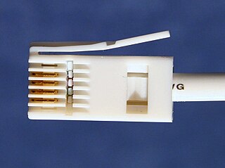
British telephone sockets were introduced in their current plug and socket form on 19 November 1981 by British Telecom to allow subscribers to connect their own telephones. The connectors are specified in British Standard BS 6312. Electrical characteristics of the telephone interface are specified by individual network operators, e.g. in British Telecom's SIN 351. Electrical characteristics required of British telephones used to be specified in BS 6305.

Plugs and sockets for electrical appliances not hardwired to mains electricity originated in the United Kingdom in the 1870s and were initially two-pin designs. These were usually sold as a mating pair, but gradually de facto and then official standards arose to enable the interchange of compatible devices. British standards have proliferated throughout large parts of the former British Empire.