A combined cycle power plant is an assembly of heat engines that work in tandem from the same source of heat, converting it into mechanical energy. On land, when used to make electricity the most common type is called a combined cycle gas turbine (CCGT) plant, which is a kind of gas-fired power plant. The same principle is also used for marine propulsion, where it is called a combined gas and steam (COGAS) plant. Combining two or more thermodynamic cycles improves overall efficiency, which reduces fuel costs.
The principle is that after completing its cycle in the first engine, the working fluid (the exhaust) is still hot enough that a second subsequent heat engine can extract energy from the heat in the exhaust. Usually the heat passes through a heat exchanger so that the two engines can use different working fluids.
By generating power from multiple streams of work, the overall efficiency can be increased by 50–60%. That is, from an overall efficiency of the system of say 34% for a simple cycle, to as much as 64% net for the turbine alone in specified conditions for a combined cycle.[1]
Historical cycles
Historically successful combined cycles have used mercury vapour turbines, magnetohydrodynamic generators and molten carbonate fuel cells, with steam plants for the low temperature "bottoming" cycle. Very low temperature bottoming cycles have been too costly due to the very large sizes of equipment needed to handle the large mass flows and small temperature differences. However, in cold climates it is common to sell hot power plant water for hot water and space heating. Vacuum-insulated piping can let this utility reach as far as 90km. The approach is called "combined heat and power" (CHP).
In stationary and marine power plants, a widely used combined cycle has a large gas turbine (operating by the Brayton cycle). The turbine's hot exhaust powers a steam power plant (operating by the Rankine cycle). This is a combined cycle gas turbine (CCGT) plant. These achieve a best-of-class real (see below) thermal efficiency of around 64% in base-load operation. In contrast, a single cycle steam power plant is limited to efficiencies from 35 to 42%. Many new power plants utilize CCGTs. Stationary CCGTs burn natural gas or synthesis gas from coal. Ships burn fuel oil.
Multiple stage turbine or steam cycles can also be used, but CCGT plants have advantages for both electricity generation and marine power. The gas turbine cycle can often start very quickly, which gives immediate power. This avoids the need for separate expensive peaker plants, or lets a ship maneuver. Over time the secondary steam cycle will warm up, improving fuel efficiency and providing further power.
The thermodynamic cycle of the basic combined cycle consists of two power plant cycles. One is the Joule or Brayton cycle which is a gas turbine cycle and the other is the Rankine cycle which is a steam turbine cycle.[5] The cycle 1-2-3-4-1 which is the gas turbine power plant cycle is the topping cycle. It depicts the heat and work transfer process taking place in the high temperature region.
The cycle a-b-c-d-e-f-a which is the Rankine steam cycle takes place at a lower temperature and is known as the bottoming cycle. Transfer of heat energy from high temperature exhaust gas to water and steam takes place in a waste heat recovery boiler in the bottoming cycle. During the constant pressure process 4-1 the exhaust gases from the gas turbine reject heat. The feed water, wet and super heated steam absorb some of this heat in the process a-b, b-c and c-d.
Steam generators
Heat transfer from hot gases to water and steam
The steam power plant takes its input heat from the high temperature exhaust gases from a gas turbine power plant.[5] The steam thus generated can be used to drive a steam turbine. The Waste Heat Recovery Boiler (WHRB) has 3 sections: Economiser, evaporator and superheater.
Cheng cycle
The Cheng cycle is a simplified form of combined cycle where the steam turbine is eliminated by injecting steam directly into the combustion turbine. This has been used since the mid 1970s and allows recovery of waste heat with less total complexity, but at the loss of the additional power and redundancy of a true combined cycle system. It has no additional steam turbine or generator, and therefore it cannot be used as a backup or supplementary power. It is named after American professor D. Y. Cheng who patented the design in 1976.[6]
Design principles
Explanation of the layout and principle of a combined cycle power generator.Working principle of a combined cycle power plant (Legend: 1-Electric generators, 2-Steam turbine, 3-Condenser, 4-Pump, 5-Boiler/heat exchanger, 6-Gas turbine)
The efficiency of a heat engine, the fraction of input heat energy that can be converted to useful work, is limited by the temperature difference between the heat entering the engine and the exhaust heat leaving the engine.
In a thermal power station, water is the working medium. High pressure steam requires strong, bulky components. High temperatures require expensive alloys made from nickel or cobalt, rather than inexpensive steel. These alloys limit practical steam temperatures to 655°C while the lower temperature of a steam plant is fixed by the temperature of the cooling water. With these limits, a steam plant has a fixed upper efficiency of 35–42%.
An open circuit gas turbine cycle has a compressor, a combustor and a turbine. For gas turbines the amount of metal that must withstand the high temperatures and pressures is small, and lower quantities of expensive materials can be used. In this type of cycle, the input temperature to the turbine (the firing temperature), is relatively high (900 to 1,400°C). The output temperature of the flue gas is also high (450 to 650°C). This is therefore high enough to provide heat for a second cycle which uses steam as the working fluid (a Rankine cycle).
In a combined cycle power plant, the heat of the gas turbine's exhaust is used to generate steam by passing it through a heat recovery steam generator (HRSG) with a live steam temperature between 420 and 580°C. The condenser of the Rankine cycle is usually cooled by water from a lake, river, sea or cooling towers. This temperature can be as low as 15°C.
Typical size
Plant size is important in the cost of the plant. The larger plant sizes benefit from economies of scale (lower initial cost per kilowatt) and improved efficiency.
For large-scale power generation, a typical set would be a 270MW primary gas turbine coupled to a 130MW secondary steam turbine, giving a total output of 400MW. A typical power station might consist of between 1 and 6 such sets.
Gas turbines for large-scale power generation are manufactured by at least four separate groups – General Electric, Siemens, Mitsubishi-Hitachi, and Ansaldo Energia. These groups are also developing, testing and/or marketing gas turbine sizes in excess of 300 MW (for 60Hz applications) and 400 MW (for 50Hz applications). Combined cycle units are made up of one or more such gas turbines, each with a waste heat steam generator arranged to supply steam to a single or multiple steam turbines, thus forming a combined cycle block or unit. Combined cycle block sizes offered by three major manufacturers (Alstom, General Electric and Siemens) can range anywhere from 50 MW to well over 1300 MW with costs approaching $670/kW.[7]
Unfired boiler
The heat recovery boiler is item 5 in the COGAS figure shown above. Hot gas turbine exhaust enters the super heater, then passes through the evaporator and finally through the economiser section as it flows out from the boiler. Feed water comes in through the economizer and then exits after having attained saturation temperature in the water or steam circuit. Finally it flows through the evaporator and super heater. If the temperature of the gases entering the heat recovery boiler is higher, then the temperature of the exiting gases is also high.[5]
Dual pressure boiler
Steam turbine plant lay out with dual pressure heat recovery boiler
Heat exchange in dual pressure heat recovery boiler
In order to remove the maximum amount of heat from the gasses exiting the high temperature cycle, a dual pressure boiler is often employed.[5] It has two water/steam drums. The low-pressure drum is connected to the low-pressure economizer or evaporator. The low-pressure steam is generated in the low temperature zone of the turbine exhaust gasses. The low-pressure steam is supplied to the low-temperature turbine. A super heater can be provided in the low-pressure circuit.
Some part of the feed water from the low-pressure zone is transferred to the high-pressure economizer by a booster pump. This economizer heats up the water to its saturation temperature. This saturated water goes through the high-temperature zone of the boiler and is supplied to the high-pressure turbine.
Supplementary firing
The HRSG can be designed to burn supplementary fuel after the gas turbine. Supplementary burners are also called duct burners. Duct burning is possible because the turbine exhaust gas (flue gas) still contains some oxygen. Temperature limits at the gas turbine inlet force the turbine to use excess air, above the optimal stoichiometric ratio to burn the fuel. Often in gas turbine designs part of the compressed air flow bypasses the burner in order to cool the turbine blades. The turbine exhaust is already hot, so a regenerative air preheater is not required as in a conventional steam plant. However, a fresh air fan blowing directly into the duct permits a duct-burning steam plant to operate even when the gas turbine cannot.
Without supplementary firing, the thermal efficiency of a combined cycle power plant is higher. But more flexible plant operations make a marine CCGT safer by permitting a ship to operate with equipment failures. A flexible stationary plant can make more money. Duct burning raises the flue temperature, which increases the quantity or temperature of the steam (e.g. to 84 bar, 525 degree Celsius). This improves the efficiency of the steam cycle. Supplementary firing lets the plant respond to fluctuations of electrical load, because duct burners can have very good efficiency with partial loads. It can enable higher steam production to compensate for the failure of another unit. Also, coal can be burned in the steam generator as an economical supplementary fuel.
Supplementary firing can raise exhaust temperatures from 600°C (GT exhaust) to 800 or even 1000°C. Supplemental firing does not raise the efficiency of most combined cycles. For single boilers it can raise the efficiency if fired to 700–750°C; for multiple boilers however, the flexibility of the plant should be the major attraction.
"Maximum supplementary firing" is the condition when the maximum fuel is fired with the oxygen available in the gas turbine exhaust.
Fuel for combined cycle power plants
Combined cycle plants are usually powered by natural gas, although fuel oil, synthesis gas or other fuels can be used. The supplementary fuel may be natural gas, fuel oil, or coal. Biofuels can also be used. Integrated solar combined cycle power stations combine the energy harvested from solar radiation with another fuel to cut fuel costs and environmental impact (See: ISCC section). Many next generation nuclear power plants can use the higher temperature range of a Brayton top cycle, as well as the increase in thermal efficiency offered by a Rankine bottoming cycle.
Where the extension of a gas pipeline is impractical or cannot be economically justified, electricity needs in remote areas can be met with small-scale combined cycle plants using renewable fuels. Instead of natural gas, these gasify and burn agricultural and forestry waste, which is often readily available in rural areas.
Managing low-grade fuels in turbines
Gas turbines burn mainly natural gas and light oil. Crude oil, residual, and some distillates contain corrosive components and as such require fuel treatment equipment. In addition, ash deposits from these fuels result in gas turbine deratings of up to 15%. They may still be economically attractive fuels however, particularly in combined-cycle plants.
Sodium and potassium are removed from residual, crude and heavy distillates by a water washing procedure. A simpler and less expensive purification system will do the same job for light crude and light distillates. A magnesium additive system may also be needed to reduce the corrosive effects if vanadium is present. Fuels requiring such treatment must have a separate fuel-treatment plant and a system of accurate fuel monitoring to assure reliable, low-maintenance operation of gas turbines.
Configuration
Combined-cycle systems can have single-shaft or multi-shaft configurations. Also, there are several configurations of steam systems.
The most fuel-efficient power generation cycles use an unfired heat recovery steam generator (HRSG) with modular pre-engineered components. These unfired steam cycles are also the lowest in initial cost, and they are often part of a single shaft system that is installed as a unit.
Supplementary-fired and multishaft combined-cycle systems are usually selected for specific fuels, applications or situations. For example, cogeneration combined-cycle systems sometimes need more heat, or higher temperatures, and electricity is a lower priority. Multishaft systems with supplementary firing can provide a wider range of temperatures or heat to electric power. Systems burning low quality fuels such as brown coal or peat might use relatively expensive closed-cycle helium turbines as the topping cycle to avoid even more expensive fuel processing and gasification that would be needed by a conventional gas turbine.
A typical single-shaft system has one gas turbine, one steam turbine, one generator and one heat recovery steam generator (HRSG). The gas turbine and steam turbine are both coupled in tandem to a single electrical generator on a single shaft. This arrangement is simpler to operate, smaller, with a lower startup cost.
Single-shaft arrangements can have less flexibility and reliability than multi-shaft systems. With some expense, there are ways to add operational flexibility: Most often, the operator desires to operate the gas turbine as a peaking plant. In these plants, the steam turbine's shaft can be disconnected with a synchro-self-shifting (SSS) clutch,[8] for start up or for simple cycle operation of the gas turbine. Another less common set of options enable more heat or standalone operation of the steam turbine to increase reliability: Duct burning, perhaps with a fresh air blower in the duct and a clutch on the gas turbine side of the shaft.
A multi-shaft system usually has only one steam system for up to three gas turbines. Having only one large steam turbine and heat sink has economies of scale and can have lower cost operations and maintenance. A larger steam turbine can also use higher pressures, for a more efficient steam cycle. However, a multi-shaft system is about 5% higher in initial cost.
The overall plant size and the associated number of gas turbines required can also determine which type of plant is more economical. A collection of single shaft combined cycle power plants can be more costly to operate and maintain, because there are more pieces of equipment. However, it can save interest costs by letting a business add plant capacity as it is needed.
Multiple-pressure reheat steam cycles are applied to combined-cycle systems with gas turbines with exhaust gas temperatures near 600°C. Single- and multiple-pressure non-reheat steam cycles are applied to combined-cycle systems with gas turbines that have exhaust gas temperatures of 540°C or less. Selection of the steam cycle for a specific application is determined by an economic evaluation that considers a plant's installed cost, fuel cost and quality, duty cycle, and the costs of interest, business risks, and operations and maintenance.
Efficiency
By combining both gas and steam cycles, high input temperatures and low output temperatures can be achieved. The efficiency of the cycles add, because they are powered by the same fuel source. So, a combined cycle plant has a thermodynamic cycle that operates between the gas-turbine's high firing temperature and the waste heat temperature from the condensers of the steam cycle. This large range means that the Carnot efficiency of the cycle is high. The actual efficiency, while lower than the Carnot efficiency, is still higher than that of either plant on its own.[9][10]
The electric efficiency of a combined cycle power station, if calculated as electric energy produced as a percentage of the lower heating value of the fuel consumed, can be over 60% when operating new, i.e. unaged, and at continuous output which are ideal conditions.
As with single cycle thermal units, combined cycle units may also deliver low temperature heat energy for industrial processes, district heating and other uses. This is called cogeneration and such power plants are often referred to as a combined heat and power (CHP) plant.
In general, combined cycle efficiencies in service are over 50% on a lower heating value and Gross Output basis. Most combined cycle units, especially the larger units, have peak, steady-state efficiencies on the LHV basis of 55 to 59%.
A limitation of combined cycles is that efficiency is reduced when not running at continuous output. During start up, the second cycle can take time to start up. Thus efficiency is initially much lower until the second cycle is running, which can take an hour or more.
Efficiency of the turbine is increased when combustion can run hotter, so the working fluid expands more. Therefore efficiency is limited by whether the first stage of turbine blades can survive higher temperatures. Cooling and materials research are continuing. A common technique, adopted from aircraft, is to pressurise hot-stage turbine blades with coolant. This is also bled-off in proprietary ways to improve the aerodynamic efficiencies of the turbine blades. Different vendors have experimented with different coolants. Air is common but steam is increasingly used. Some vendors might now utilize single-crystal turbine blades in the hot section, a technique already common in military aircraft engines.
The efficiency of CCGT and GT can also be boosted by pre-cooling combustion air. This increases its density, also increasing the expansion ratio of the turbine. This is practised in hot climates and also has the effect of increasing power output. This is achieved by evaporative cooling of water using a moist matrix placed in the turbine's inlet, or by using Ice storage air conditioning. The latter has the advantage of greater improvements due to the lower temperatures available. Furthermore, ice storage can be used as a means of load control or load shifting since ice can be made during periods of low power demand and, potentially in the future the anticipated high availability of other resources such as renewables during certain periods.
Combustion technology is a proprietary but very active area of research, because fuels, gasification and carburation all affect fuel efficiency. A typical focus is to combine aerodynamic and chemical computer simulations to find combustor designs that assure complete fuel burn up, yet minimize both pollution and dilution of the hot exhaust gases. Some combustors inject other materials, such air or steam, to reduce pollution by reducing the formation of nitrates and ozone.
Another active area of research is the steam generator for the Rankine cycle. Typical plants already use a two-stage steam turbine, reheating the steam between the two stages. When the heat-exchangers' thermal conductivity can be improved, efficiency improves. As in nuclear reactors, tubes might be made thinner (e.g. from stronger or more corrosion-resistant steel). Another approach might use silicon carbide sandwiches, which do not corrode.[11]
There is also some development of modified Rankine cycles. Two promising areas are ammonia/water mixtures,[12] and turbines that utilize supercritical carbon dioxide.[13]
Modern CCGT plants also need software that is precisely tuned to every choice of fuel, equipment, temperature, humidity and pressure. When a plant is improved, the software becomes a moving target. CCGT software is also expensive to test, because actual time is limited on the multimillion-dollar prototypes of new CCGT plants. Testing usually simulates unusual fuels and conditions, but validates the simulations with selected data points measured on actual equipment.
Competition
There is active competition to reach higher efficiencies. Research aimed at 1,370°C (2,500°F) turbine inlet temperature has led to even more efficient combined cycles.[citation needed]
Nearly 60% LHV efficiency (54% HHV efficiency) was reached in the Baglan Bay power station, using a GE H-technology gas turbine with a NEM 3 pressure reheat boiler, using steam from the heat recovery steam generator (HRSG) to cool the turbine blades.[citation needed]
In May 2011 Siemens AG announced they had achieved a 60.75% efficiency with a 578 megawatt SGT5-8000H gas turbine at the Irsching Power Station.[14]
On April 28, 2016, the plant run by Électricité de France in Bouchain was certified by Guinness World Records as the worlds most efficient combined cycle power plant at 62.22%. It uses a General Electric 9HA, that claimed 41.5% simple cycle efficiency and 61.4% in combined cycle mode, with a gas turbine output of 397 MW to 470 MW and a combined output of 592 MW to 701 MW. Its firing temperature is between 2,600 and 2,900°F (1,430 and 1,590°C), its overall pressure ratio is 21.8 to 1.[16]
In December 2016, Mitsubishi claimed a LHV efficiency of greater than 63% for some members of its J Series turbines.[17]
In December 2017, GE claimed 64% in its latest 826 MW HA plant, up from 63.7%. They said this was due to advances in additive manufacturing and combustion. Their press release said that they planned to achieve 65% by the early 2020s.[1]
An integrated gasification combined cycle, or IGCC, is a power plant using synthesis gas (syngas). Syngas can be produced from a number of sources, including coal and biomass. The system uses gas and steam turbines, the steam turbine operating from the heat left over from the gas turbine. This process can raise electricity generation efficiency to around 50%.
Integrated solar combined cycle (ISCC)
An Integrated Solar Combined Cycle (ISCC) is a hybrid technology in which a solar thermal field is integrated within a combined cycle plant. In ISCC plants, solar energy is used as an auxiliary heat supply, supporting the steam cycle, which results in increased generation capacity or a reduction of fossil fuel use.[18]
Thermodynamic benefits are that daily steam turbine startup losses are eliminated.[19]
Major factors limiting the load output of a combined cycle power plant are the allowed pressure and temperature transients of the steam turbine and the heat recovery steam generator waiting times to establish required steam chemistry conditions and warm-up times for the balance of plant and the main piping system. Those limitations also influence the fast start-up capability of the gas turbine by requiring waiting times. And waiting gas turbines consume gas. The solar component, if the plant is started after sunshine, or before, if there is heat storage, allows the preheat of the steam to the required conditions. That is, the plant is started faster and with less consumption of gas before achieving operating conditions.[20] Economic benefits are that the solar components costs are 25% to 75% those of a Solar Energy Generating Systems plant of the same collector surface.[21]
In most successful combined cycles, the bottoming cycle for power is a conventional steam Rankine cycle.
It is already common in cold climates (such as Finland) to drive community heating systems from a steam power plant's condenser heat. Such cogeneration systems can yield theoretical efficiencies above 95%.
Bottoming cycles producing electricity from the steam condenser's heat exhaust are theoretically possible, but conventional turbines are uneconomically large. The small temperature differences between condensing steam and outside air or water require very large movements of mass to drive the turbines.
Although not reduced to practice, a vortex of air can concentrate the mass flows for a bottoming cycle. Theoretical studies of the Vortex engine show that if built at scale it is an economical bottoming cycle for a large steam Rankine cycle power plant.
A steam engine is a heat engine that performs mechanical work using steam as its working fluid. The steam engine uses the force produced by steam pressure to push a piston back and forth inside a cylinder. This pushing force can be transformed, by a connecting rod and crank, into rotational force for work. The term "steam engine" is most commonly applied to reciprocating engines as just described, although some authorities have also referred to the steam turbine and devices such as Hero's aeolipile as "steam engines". The essential feature of steam engines is that they are external combustion engines, where the working fluid is separated from the combustion products. The ideal thermodynamic cycle used to analyze this process is called the Rankine cycle. In general usage, the term steam engine can refer to either complete steam plants, such as railway steam locomotives and portable engines, or may refer to the piston or turbine machinery alone, as in the beam engine and stationary steam engine.
A power station, also referred to as a power plant and sometimes generating station or generating plant, is an industrial facility for the generation of electric power. Power stations are generally connected to an electrical grid.
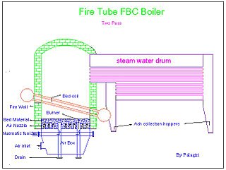
Fluidized bed combustion (FBC) is a combustion technology used to burn solid fuels.
The Rankine cycle is an idealized thermodynamic cycle describing the process by which certain heat engines, such as steam turbines or reciprocating steam engines, allow mechanical work to be extracted from a fluid as it moves between a heat source and heat sink. The Rankine cycle is named after William John Macquorn Rankine, a Scottish polymath professor at Glasgow University.
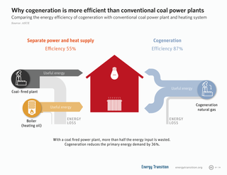
Cogeneration or combined heat and power (CHP) is the use of a heat engine or power station to generate electricity and useful heat at the same time.
A magnetohydrodynamic generator is a magnetohydrodynamic converter that transforms thermal energy and kinetic energy directly into electricity. An MHD generator, like a conventional generator, relies on moving a conductor through a magnetic field to generate electric current. The MHD generator uses hot conductive ionized gas as the moving conductor. The mechanical dynamo, in contrast, uses the motion of mechanical devices to accomplish this.
A feedwater heater is a power plant component used to pre-heat water delivered to a steam generating boiler. Preheating the feedwater reduces the irreversibilities involved in steam generation and therefore improves the thermodynamic efficiency of the system. This reduces plant operating costs and also helps to avoid thermal shock to the boiler metal when the feedwater is introduced back into the steam cycle.
A thermal power station is a type of power station in which heat energy is converted to electrical energy. In a steam-generating cycle heat is used to boil water in a large pressure vessel to produce high-pressure steam, which drives a steam turbine connected to an electrical generator. The low-pressure exhaust from the turbine enters a steam condenser where it is cooled to produce hot condensate which is recycled to the heating process to generate more high pressure steam. This is known as a Rankine cycle.
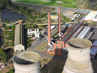
Cockenzie power station was a coal-fired power station in East Lothian, Scotland. It was situated on the south shore of the Firth of Forth, near the town of Cockenzie and Port Seton, 8 mi (13 km) east of the Scottish capital of Edinburgh. The station dominated the local coastline with its distinctive twin chimneys from 1967 until the chimneys' demolition in September 2015. Initially operated by the nationalised South of Scotland Electricity Board, it was operated by Scottish Power following the privatisation of the industry in 1991. In 2005 a WWF report named Cockenzie as the UK's least carbon-efficient power station, in terms of carbon dioxide released per unit of energy generated.
The steam-electric power station is a power station in which the electric generator is steam driven. Water is heated, turns into steam and spins a steam turbine which drives an electrical generator. After it passes through the turbine, the steam is condensed in a condenser. The greatest variation in the design of steam-electric power plants is due to the different fuel sources.
A turboexpander, also referred to as a turbo-expander or an expansion turbine, is a centrifugal or axial-flow turbine, through which a high-pressure gas is expanded to produce work that is often used to drive a compressor or generator.
A mercury vapour turbine is a form of heat engine that uses mercury as the working fluid of its thermal cycle. A mercury vapour turbine has been used in conjunction with a steam turbine for generating electricity. This example of combined cycle generation was not widely adopted, because of high capital cost and the obvious toxic hazard if the mercury leaked into the environment.
In thermal engineering, the organic Rankine cycle (ORC) is a type of thermodynamic cycle. It is a variation of the Rankine cycle named for its use of an organic, high-molecular-mass fluid whose vaporization temperature is lower than that of water. The fluid allows heat recovery from lower-temperature sources such as biomass combustion, industrial waste heat, geothermal heat, solar ponds etc. The low-temperature heat is converted into useful work, that can itself be converted into electricity.
Damhead Creek power station is a 792 MWe gas-fired power station in Kent, England, on the Hoo Peninsula, It is near the site of the decommissioned Kingsnorth power station. The plant entered service in February 2001.
Grain Power Station is a 1,275 megawatts (1,710,000 hp) operational CCGT power station in Kent, England, owned by Uniper. It was also the name of an oil-fired, now demolished, 1,320MW power station in operation from 1979 to 2012.
Carrington Power Station is a combined cycle gas turbine power station, which was completed in Autumn 2016 and began commercial operation on 18 September 2016. It is located on the site of a former coal-fired power station, close to the villages of Carrington and Partington in the Greater Manchester Area and 12 km (7.5 mi) southwest of Manchester City Centre. The Manchester Ship Canal and the River Mersey run alongside the site, in Trafford, Greater Manchester, in North West England.
A waste heat recovery unit (WHRU) is an energy recovery heat exchanger that transfers heat from process outputs at high temperature to another part of the process for some purpose, usually increased efficiency. The WHRU is a tool involved in cogeneration. Waste heat may be extracted from sources such as hot flue gases from a diesel generator, steam from cooling towers, or even waste water from cooling processes such as in steel cooling.
Repowering is the process of replacing older power stations with newer ones that either have a greater nameplate capacity or more efficiency which results in a net increase of power generated. Repowering can happen in several different ways. It can be as small as switching out and replacing a boiler, to as large as replacing the entire system to create a more powerful system entirely. There are many upsides to repowering.
The Hygroscopic cycle is a thermodynamic cycle converting thermal energy into mechanical power by the means of a steam turbine. It is similar to the Rankine cycle using water as the motive fluid but with the novelty of introducing salts and their hygroscopic properties for the condensation. The salts are desorbed in the boiler or steam generator, where clean steam is released and superheated in order to be expanded and generate power through the steam turbine. Boiler blowdown with the concentrated hygroscopic compounds is used thermally to pre-heat the steam turbine condensate, and as reflux in the steam-absorber.
Termosolar Borges is a hybrid biomass-parabolic trough solar thermal power plant which provides electricity to Spain's transmission system. It is located about 100 kilometres (62 mi) west of Barcelona, about 10 kilometres (6.2 mi) south-east of Lleida, near Les Borges Blanques, Catalonia, Spain.
↑ Wagar, W.R.; Zamfirescu, C.; Dincer, I. (December 2010). "Thermodynamic performance assessment of an ammonia–water Rankine cycle for power and heat production". Energy Conversion and Management. 51 (12): 2501–2509. Bibcode:2010ECM....51.2501W. doi:10.1016/j.enconman.2010.05.014.
↑ Dostal, Vaclav. "A Supercritical Carbondioxide Cycle for Next Generation Nuclear Reactors" (Document). MIT.
Steam & Gas Turbines And Power Plant Engineering ISBN C039000000001, R Yadav., Sanjay., Rajay, Central Publishing House, Allahabad
Applied Thermodynamics ISBN9788185444031, R Yadav., Sanjay., Rajay, Central Publishing House, Allahabad.
Sanjay; Singh, Onkar; Prasad, B. N. (2003). "Thermodynamic Evaluation of Advanced Combined Cycle Using Latest Gas Turbine". Volume 3: Turbo Expo 2003. pp.95–101. doi:10.1115/GT2003-38096. ISBN0-7918-3686-X.
This page is based on this Wikipedia article Text is available under the CC BY-SA 4.0 license; additional terms may apply. Images, videos and audio are available under their respective licenses.