Ericsson cycle

Last updated
Rendering of an Ericsson engine. A cold gaseous working fluid, such as atmospheric air (shown in blue), enters the cylinder via a non-return valve at the top-right. The air is compressed by the piston (black) as the piston moves upward. The compressed air is stored in the pneumatic tank (at left). A two-way valve (gray) moves downward to allow pressurized air to pass through the regenerator where it is preheated. The air then enters the space below the piston, which is an externally heated expansion-chamber. The air expands and does work on the piston as it moves upward. After the expansion stroke, the two-way valve moves upward, thus closing off the tank and opening the exhaust port. As the piston moves back downward in the exhaust stroke, hot air is pushed back through the regenerator, which reclaims most of the heat, before passing out the exhaust port (left) as cool air. Ericsson engine4.PNG
Rendering of an Ericsson engine. A cold gaseous working fluid, such as atmospheric air (shown in blue), enters the cylinder via a non-return valve at the top-right. The air is compressed by the piston (black) as the piston moves upward. The compressed air is stored in the pneumatic tank (at left). A two-way valve (gray) moves downward to allow pressurized air to pass through the regenerator where it is preheated. The air then enters the space below the piston, which is an externally heated expansion-chamber. The air expands and does work on the piston as it moves upward. After the expansion stroke, the two-way valve moves upward, thus closing off the tank and opening the exhaust port. As the piston moves back downward in the exhaust stroke, hot air is pushed back through the regenerator, which reclaims most of the heat, before passing out the exhaust port (left) as cool air.

The Ericsson cycle is named after inventor John Ericsson who designed and built many unique heat engines based on various thermodynamic cycles. He is credited with inventing two unique heat engine cycles and developing practical engines based on these cycles. His first cycle is now known as the closed Brayton cycle, while his second cycle is what is now called the Ericsson cycle. Ericsson is one of the few who built open-cycle engines, [1] but he also built closed-cycle ones. [2]

Contents

Ideal Ericsson cycle

Ideal Ericsson cycle Ericsson-Prozess Diagramme.png
Ideal Ericsson cycle

The following is a list of the four processes that occur between the four stages of the ideal Ericsson cycle:

Comparison with Carnot, Diesel, Otto, and Stirling cycles

The ideal Otto and Diesel cycles are not totally reversible because they involve heat transfer through a finite temperature difference during the irreversible isochoric/isobaric heat-addition and isochoric heat-rejection processes. The aforementioned irreversibility renders the thermal efficiency of these cycles less than that of a Carnot engine operating within the same limits of temperature. Another cycle that features isobaric heat-addition and heat-rejection processes is the Ericsson cycle. The Ericsson cycle is an altered version of the Carnot cycle in which the two isentropic processes featured in the Carnot cycle are replaced by two isothermal regeneration processes.

The Ericsson cycle is often compared with the Stirling cycle, since the engine designs based on these respective cycles are both external combustion engines with regenerators. The Ericsson is perhaps most similar to the so-called "double-acting" type of Stirling engine, in which the displacer piston also acts as the power piston. Theoretically, both of these cycles have so called ideal efficiency, which is the highest allowed by the second law of thermodynamics. The most well-known ideal cycle is the Carnot cycle, although a useful Carnot engine is not known to have been invented. The theoretical efficiencies for both, Ericsson and Stirling cycles acting in the same limits are equal to the Carnot Efficiency for same limits.

Comparison with the Brayton cycle

The first cycle Ericsson developed is now called the "Brayton cycle", commonly applied to gas turbine engines.

The second Ericsson cycle is the cycle most commonly referred to as simply the "Ericsson cycle". The (second) Ericsson cycle is also the limit of an ideal gas-turbine Brayton cycle, operating with multistage intercooled compression, and multistage expansion with reheat and regeneration. Compared to the Brayton cycle which uses adiabatic compression and expansion, the second Ericsson cycle uses isothermal compression and expansion, thus producing more net work per stroke. Also the use of regeneration in the Ericsson cycle increases efficiency by reducing the required heat input. For further comparisons of thermodynamic cycles, see heat engine.

Cycle/ProcessCompressionHeat additionExpansionHeat rejection
Ericsson (First, 1833) adiabatic isobaric adiabatic isobaric
Ericsson (Second, 1853) isothermal isobaric isothermal isobaric
Brayton (Turbine) adiabatic isobaric adiabatic isobaric

Ericsson engine

Ericsson Caloric engine Ericsson Caloric engine.jpg
Ericsson Caloric engine
Ericsson Caloric Engine Ericsson Caloric Engine.JPG
Ericsson Caloric Engine

The Ericsson engine is based on the Ericsson cycle, and is known as an "external combustion engine", because it is externally heated. To improve efficiency, the engine has a regenerator or recuperator between the compressor and the expander. The engine can be run open- or closed-cycle. Expansion occurs simultaneously with compression, on opposite sides of the piston.

Regenerator

Ericsson coined the term "regenerator" for his independent invention of the mixed-flow counter-current heat exchanger. However, Rev. Robert Stirling had invented the same device, prior to Ericsson, so the invention is credited to Stirling. Stirling called it an "economiser" or "economizer", because it increased the fuel economy of various types of heat processes. The invention was found to be useful, in many other devices and systems, where it became more widely used, since other types of engines became favored over the Stirling engine. The term "regenerator" is now the name given to the component in the Stirling engine.

The term "recuperator" refers to a separated-flow, counter-current heat exchanger. As if this weren't confusing enough, a mixed-flow regenerator is sometimes used as a quasi-separated-flow recuperator. This can be done through the use of moving valves, or by a rotating regenerates with fixed baffles, or by the use of other moving parts. When heat is recovered from exhaust gases and used to preheat combustion air, typically the term recuperator is used, because the two flows are separate.

History

In 1791, before Ericsson, John Barber proposed a similar engine. The Barber engine used a bellows compressor and a turbine expander, but it lacked a regenerator/recuperator. There are no records of a working Barber engine. Ericsson invented and patented his first engine using an external version of the Brayton cycle in 1833 (number 6409/1833 British). This was 18 years before Joule and 43 years before Brayton. Brayton engines were all piston engines and for the most part, internal combustion versions of the un-recuperated Ericsson engine. The "Brayton cycle" is now known as the gas turbine cycle, which differs from the original "Brayton cycle" in the use of a turbine compressor and expander. The gas turbine cycle is used for all modern gas turbine and turbojet engines, however simple cycle turbines are often recuperated to improve efficiency and these recuperated turbines more closely resemble Ericsson's work.

Ericsson eventually abandoned the open cycle in favor of the traditional closed Stirling cycle.

Ericsson's engine can easily be modified to operate in a closed-cycle mode, using a second, lower-pressure, cooled container between the original exhaust and intake. In closed cycle, the lower pressure can be significantly above ambient pressure, and He or H2 working gas can be used. Because of the higher pressure difference between the upward and downward movement of the work-piston, specific output can be greater than of a valveless Stirling engine. The added cost is the valve. Ericsson's engine also minimizes mechanical losses: the power necessary for compression does not go through crank-bearing frictional losses, but is applied directly from the expansion force. The piston-type Ericsson engine can potentially be the highest efficiency heat engine arrangement ever constructed. Admittedly, this has yet to be proven in practical applications.[ citation needed ]

Ericsson designed and built a very great number of engines running on various cycles including steam, Stirling, Brayton, externally heated diesel air fluid cycle. He ran his engines on a great variety of fuels including coal and solar heat.

Ericsson was also responsible for an early use of the screw propeller for ship propulsion, in the USS Princeton, built in 1842–43.

Caloric ship Ericsson

In 1851 the Ericsson-cycle engine (the second of the two discussed here) was used to power a 2,000-ton ship, the caloric ship Ericsson, [3] and ran flawlessly for 73 hours. [4] The combination engine produced about 300 horsepower (220 kW). It had a combination of four dual-piston engines; the larger expansion piston/cylinder, at 14 feet (4.3 m) in diameter, was perhaps the largest piston ever built. Rumor has it that tables were placed on top of those pistons (obviously in the cool compression chamber, not the hot power chamber) and dinner was served and eaten, while the engine was running at full power.[ citation needed ] At 6.5  RPM the pressure was limited to 8 psi (55 kPa). According to the official report it only consumed 4200 kg coal per 24 hours (original target was 8000 kg, which is still better than contemporary steam engines). The one sea trial proved that even though the engine ran well, the ship was underpowered. Some time after the trials, the Ericsson sank. When it was raised, the Ericsson-cycle engine was removed and a steam engine took its place. The ship was wrecked when blown aground in November 1892 at the entrance to Barkley Sound, British Columbia, Canada. [5]

Today's potential

The Ericsson cycle (and the similar Brayton cycle) receives renewed interest [6] today to extract power from the exhaust heat of gas (and producer gas) engines and solar concentrators. An important advantage of the Ericsson cycle over the widely known Stirling engine is often not recognized : the volume of the heat exchanger does not adversely affect the efficiency.

(...)despite having significant advantages over the Stirling. Amongst them, it is worth to note that the Ericsson engine heat exchangers are not dead volumes, whereas the Stirling engine heat exchangers designer has to face a difficult compromise between as large heat transfer areas as possible, but as small heat exchanger volumes as possible. [7]

For medium and large engines the cost of valves can be small compared to this advantage. Turbocompressor plus turbine implementations seem favorable in the MWe range, positive displacement compressor plus turbine for Nx100 kWe power, and positive displacement compressor+expander below 100 kW. With high temperature hydraulic fluid, both the compressor and the expander can be liquid-ring pumps even up to 400 °C, with rotating casing for best efficiency.

Related Research Articles

<span class="mw-page-title-main">Carnot heat engine</span> Theoretical engine

A Carnot heat engine is a theoretical heat engine that operates on the Carnot cycle. The basic model for this engine was developed by Nicolas Léonard Sadi Carnot in 1824. The Carnot engine model was graphically expanded by Benoît Paul Émile Clapeyron in 1834 and mathematically explored by Rudolf Clausius in 1857, work that led to the fundamental thermodynamic concept of entropy. The Carnot engine is the most efficient heat engine which is theoretically possible. The efficiency depends only upon the absolute temperatures of the hot and cold heat reservoirs between which it operates.

<span class="mw-page-title-main">Heat engine</span> System that converts heat or thermal energy to mechanical work

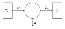
A heat engine is a system that converts heat to usable energy, particularly mechanical energy, which can then be used to do mechanical work. While originally conceived in the context of mechanical energy, the concept of the heat engine has been applied to various other kinds of energy, particularly electrical, since at least the late 19th century. The heat engine does this by bringing a working substance from a higher state temperature to a lower state temperature. A heat source generates thermal energy that brings the working substance to the higher temperature state. The working substance generates work in the working body of the engine while transferring heat to the colder sink until it reaches a lower temperature state. During this process some of the thermal energy is converted into work by exploiting the properties of the working substance. The working substance can be any system with a non-zero heat capacity, but it usually is a gas or liquid. During this process, some heat is normally lost to the surroundings and is not converted to work. Also, some energy is unusable because of friction and drag.

<span class="mw-page-title-main">Stirling engine</span> Closed-cycle regenerative heat engine

A Stirling engine is a heat engine that is operated by the cyclic compression and expansion of air or other gas between different temperatures, resulting in a net conversion of heat energy to mechanical work.

<span class="mw-page-title-main">Stirling cycle</span> Thermodynamic cycle that includes the basic Stirling engine

The Stirling cycle is a thermodynamic cycle that describes the general class of Stirling devices. This includes the original Stirling engine that was invented, developed and patented in 1816 by Robert Stirling with help from his brother, an engineer.

<span class="mw-page-title-main">Thermoacoustic heat engine</span> Heat pump powered by sound

Thermoacoustic engines are thermoacoustic devices which use high-amplitude sound waves to pump heat from one place to another or use a heat difference to produce work in the form of sound waves.

<span class="mw-page-title-main">Brayton cycle</span> Thermodynamic cycle

The Brayton cycle, also known as the Joule cycle, is a thermodynamic cycle that describes the operation of certain heat engines that have air or some other gas as their working fluid. It is characterized by isentropic compression and expansion, and isobaric heat addition and rejection, though practical engines have adiabatic rather than isentropic steps.

<span class="mw-page-title-main">Compressed-air energy storage</span> Method for matching variable production with demand

Compressed-air energy storage (CAES) is a way to store energy for later use using compressed air. At a utility scale, energy generated during periods of low demand can be released during peak load periods.

<span class="mw-page-title-main">Compressor</span> Machine to increase pressure of gas by reducing its volume

A compressor is a mechanical device that increases the pressure of a gas by reducing its volume. An air compressor is a specific type of gas compressor.

<span class="mw-page-title-main">Rankine cycle</span> Model that is used to predict the performance of steam turbine systems

The Rankine cycle is an idealized thermodynamic cycle describing the process by which certain heat engines, such as steam turbines or reciprocating steam engines, allow mechanical work to be extracted from a fluid as it moves between a heat source and heat sink. The Rankine cycle is named after William John Macquorn Rankine, a Scottish polymath professor at Glasgow University.

A refrigerator designed to reach cryogenic temperatures is often called a cryocooler. The term is most often used for smaller systems, typically table-top size, with input powers less than about 20 kW. Some can have input powers as low as 2–3 W. Large systems, such as those used for cooling the superconducting magnets in particle accelerators are more often called cryogenic refrigerators. Their input powers can be as high as 1 MW. In most cases cryocoolers use a cryogenic fluid as the working substance and employ moving parts to cycle the fluid around a thermodynamic cycle. The fluid is typically compressed at room temperature, precooled in a heat exchanger, then expanded at some low temperature. The returning low-pressure fluid passes through the heat exchanger to precool the high-pressure fluid before entering the compressor intake. The cycle is then repeated.

<span class="mw-page-title-main">Hot air engine</span> External combustion engine using air as the working fluid

A hot air engine is any heat engine that uses the expansion and contraction of air under the influence of a temperature change to convert thermal energy into mechanical work. These engines may be based on a number of thermodynamic cycles encompassing both open cycle devices such as those of Sir George Cayley and John Ericsson and the closed cycle engine of Robert Stirling. Hot air engines are distinct from the better known internal combustion based engine and steam engine.

<span class="mw-page-title-main">Thermodynamic cycle</span> Linked cyclic series of thermodynamic processes

A thermodynamic cycle consists of linked sequences of thermodynamic processes that involve transfer of heat and work into and out of the system, while varying pressure, temperature, and other state variables within the system, and that eventually returns the system to its initial state. In the process of passing through a cycle, the working fluid (system) may convert heat from a warm source into useful work, and dispose of the remaining heat to a cold sink, thereby acting as a heat engine. Conversely, the cycle may be reversed and use work to move heat from a cold source and transfer it to a warm sink thereby acting as a heat pump. If at every point in the cycle the system is in thermodynamic equilibrium, the cycle is reversible. Whether carried out reversible or irreversibly, the net entropy change of the system is zero, as entropy is a state function.

<span class="mw-page-title-main">Thermal efficiency</span> Performance measure of a device that uses thermal energy

In thermodynamics, the thermal efficiency is a dimensionless performance measure of a device that uses thermal energy, such as an internal combustion engine, steam turbine, steam engine, boiler, furnace, refrigerator, ACs etc.

Economizers, or economisers (UK), are mechanical devices intended to reduce energy consumption, or to perform useful function such as preheating a fluid. The term economizer is used for other purposes as well. Boiler, power plant, heating, refrigeration, ventilating, and air conditioning (HVAC) uses are discussed in this article. In simple terms, an economizer is a heat exchanger.

<span class="mw-page-title-main">Turboexpander</span> Type of turbine for high-pressure gas

A turboexpander, also referred to as a turbo-expander or an expansion turbine, is a centrifugal or axial-flow turbine, through which a high-pressure gas is expanded to produce work that is often used to drive a compressor or generator.

<span class="mw-page-title-main">Carnot cycle</span> Idealized thermodynamic cycle

A Carnot cycle is an ideal thermodynamic cycle proposed by French physicist Sadi Carnot in 1824 and expanded upon by others in the 1830s and 1840s. By Carnot's theorem, it provides an upper limit on the efficiency of any classical thermodynamic engine during the conversion of heat into work, or conversely, the efficiency of a refrigeration system in creating a temperature difference through the application of work to the system.

Engine efficiency of thermal engines is the relationship between the total energy contained in the fuel, and the amount of energy used to perform useful work. There are two classifications of thermal engines-

  1. Internal combustion and
  2. External combustion engines.

In aeronautical engineering, overall pressure ratio, or overall compression ratio, is the ratio of the stagnation pressure as measured at the front and rear of the compressor of a gas turbine engine. The terms compression ratio and pressure ratio are used interchangeably. Overall compression ratio also means the overall cycle pressure ratio which includes intake ram.

<span class="mw-page-title-main">Heat pump and refrigeration cycle</span> Mathematical models of heat pumps and refrigeration

Thermodynamic heat pump cycles or refrigeration cycles are the conceptual and mathematical models for heat pump, air conditioning and refrigeration systems. A heat pump is a mechanical system that allows for the transmission of heat from one location at a lower temperature to another location at a higher temperature. Thus a heat pump may be thought of as a "heater" if the objective is to warm the heat sink, or a "refrigerator" or “cooler” if the objective is to cool the heat source. In either case, the operating principles are similar. Heat is moved from a cold place to a warm place.

<span class="mw-page-title-main">Humphrey cycle</span> Thermodynamic cycle

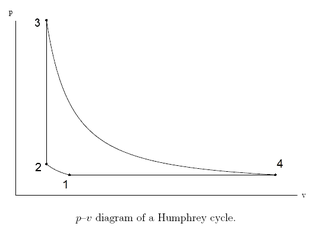
The Humphrey cycle is a thermodynamic cycle similar to the pulse detonation engine and pulse compression detonation system cycles. It may be considered to be a modification of the Brayton cycle in which the constant-pressure heat addition process of the Brayton cycle is replaced by a constant-volume heat addition process.

References

  1. "Ericsson's open-cycle engine of 1852". hotairengines.org.
  2. "Ericsson's closed-cycle engine of 1833". hotairengines.org.
  3. "Ericsson's Caloric Ship". hotairengines.org.
  4. "Ericsson Caloric Engine". Genuineideas.com. Retrieved 2015-12-15.
  5. "Graveyard of the Pacific - the Shipwrecks of Vancouver Island". www.pacificshipwrecks.ca. Archived from the original on 10 July 2004. Retrieved 13 January 2022.
  6. "Projects - detail". Assystem. 2015-11-18. Archived from the original on 2015-12-22. Retrieved 2015-12-15.
  7. Fula A, Stouffs P, Sierra F (22 March 2013). In-Cylinder Heat Transfer in an Ericsson Engine Prototype (PDF). International Conference on Renewable Energies and Power Quality (ICREPQ’13). Bilbao Spain.