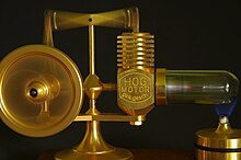
A model of a Stirling engine showing its simplicity. Unlike the steam engine or internal combustion engine, it has no valves or timing train. The heat source (not shown) would be placed under the brass cylinder.
A Stirling engine is a heat engine that is operated by the cyclic expansion and contraction of air or other gas (the working fluid) by exposing it to different temperatures, resulting in a net conversion of heat energy to mechanical work.[1][2]
More specifically, the Stirling engine is a closed-cycle regenerative heat engine, with a permanent gaseous working fluid. Closed-cycle, in this context, means a thermodynamic system in which the working fluid is permanently contained within the system. Regenerative describes the use of a specific type of internal heat exchanger and thermal store, known as the regenerator. Strictly speaking, the inclusion of the regenerator is what differentiates a Stirling engine from other closed-cycle hot air engines.[3]
In the Stirling engine, a working fluid (e.g. air) is heated by energy supplied from outside the engine's interior space (cylinder). As the fluid expands, mechanical work is extracted by a piston, which is coupled to a displacer. The displacer moves the working fluid to a different location within the engine, where it is cooled, which creates a partial vacuum at the working cylinder, and more mechanical work is extracted. The displacer moves the cooled fluid back to the hot part of the engine, and the cycle continues.
A unique feature is the regenerator, which acts as a temporary heat store by retaining heat within the machine rather than dumping it into the heat sink, thereby increasing its efficiency.
The heat is supplied from the outside, so the hot area of the engine can be warmed with any external heat source. Similarly, the cooler part of the engine can be maintained by an external heat sink, such as running water or air flow. The gas is permanently retained in the engine, allowing a gas with the most-suitable properties to be used, such as helium or hydrogen. There are no intake and no exhaust gas flows so the machine is practically silent.
The machine is reversible so that if the shaft is turned by an external power source a temperature difference will develop across the machine; in this way it acts as a heat pump.
The Stirling engine was invented by Scotsman Robert Stirling[4] in 1816 as an industrial prime mover to rival the steam engine, and its practical use was largely confined to low-power domestic applications for over a century.[5]
This article may need to be rewritten to comply with Wikipedia's quality standards, as section.You can help. The talk page may contain suggestions.(June 2021)
Illustration from Robert Stirling's 1816 patent application of the air engine design that later came to be known as the Stirling Engine
Early hot air engines
Robert Stirling is considered one of the fathers of hot air engines, along with earlier innovators such as Guillaume Amontons,[6] who built the first working hot air engine in 1699.[7]
Amontons was later followed by Sir George Cayley.[8] This engine type was of those in which the fire is enclosed, and fed by air pumped in beneath the grate in sufficient quantity to maintain combustion, while by far the largest portion of the air enters above the fire, to be heated and expanded; the whole, together with the products of combustion, then acts on the piston, and passes through the working cylinder; and the operation being one of simple mixture only, no heating surface of metal is required, the air to be heated being brought into immediate contact with the fire.[citation needed]
Stirling came up with a first air engine in 1816.[9] The principle of the Stirling Air Engine differs from that of Sir George Cayley (1807), in which the air is forced through the furnace and exhausted, whereas in Stirling's engine the air works in a closed circuit. The inventor devoted most of his attention to that.[citation needed]
A 2-horsepower (1.5kW) engine, built in 1818 for pumping water at an Ayrshire quarry, continued to work for some time until a careless attendant allowed the heater to become overheated. This experiment proved to the inventor that, owing to the low working pressure obtainable, the engine could only be adapted to low power for which there was, at that time, no demand.[citation needed]
The Stirling 1816 patent[10] was also about an "economiser," which is the predecessor of the regenerator. In this patent (# 4081) he describes the "economiser" technology and several applications where such technology can be used. Out of them came a new arrangement for a hot air engine.[citation needed]
With his brother James, Stirling patented a second hot air engine in 1827.[11] They inverted the design so that the hot ends of the displacers were underneath the machinery, and they added a compressed air pump so the air within could be increased in pressure to around 20 standard atmospheres (2,000kPa).[citation needed]
The Stirling brothers were followed shortly after (1828) by Parkinson & Crossley[12] and Arnott[13] in 1829.[citation needed]
These precursors, including Ericsson,[14] have brought to the world the hot air engine technology and its enormous advantages over the steam engine.[citation needed] Each came with his own specific technology, and although the Stirling engine and the Parkinson & Crossley engines were quite similar, Robert Stirling distinguished himself by inventing the regenerator.[citation needed]
Parkinson and Crossley introduced the principle of using air of greater density than that of the atmosphere and so obtained an engine of greater power in the same compass. James Stirling followed this same idea when he built the famous Dundee engine.[15]
The Stirling patent of 1827 was the base of the Stirling third patent of 1840.[16] The changes from the 1827 patent were minor but essential, and this third patent led to the Dundee engine.[17]
James Stirling presented his engine to the Institution of Civil Engineers in 1845, [18] the first engine of this kind which, after various modifications, was efficiently constructed and heated, had a cylinder of 30 centimetres (12 inches) in diameter, with a length of stroke of 60 centimetres (2ft), and made 40 strokes or revolutions in a minute (40rpm). This engine moved all the machinery at the Dundee Foundry Company's works for eight or ten months, and was previously found capable of raising 320,000kg (700,000lbs) 60cm (2ft) in a minute, a power of approximately 16 kilowatts (21 horsepower).[citation needed] Finding this power insufficient for their works, the Dundee Foundry Company erected the second engine with a cylinder of 40 centimetres (16 inches) in diameter, a stroke of 1.2 metres (4 feet), and making 28 strokes in a minute. When this engine had been in continuous operation for over two years it had not only performed the work of the foundry in the most satisfactory manner but had been tested (by a friction brake on a third mover) to the extent of lifting nearly 687 tonnes (1,500,000 pounds), approximately 34 kilowatts (45 horsepower).[citation needed]
Invention and early development
The Stirling engine (or Stirling's air engine as it was known at the time) was invented and patented in 1816.[19] It followed earlier attempts at making an air engine but was probably the first put to practical use when, in 1818, an engine built by Stirling was employed pumping water in a quarry.[20] The main subject of Stirling's original patent was a heat exchanger, which he called an "economiser" for its enhancement of fuel economy in a variety of applications. The patent also described in detail the employment of one form of the economiser in his unique closed-cycle air engine design[21] in which application it is now generally known as a "regenerator". Subsequent development by Robert Stirling and his brother James, an engineer, resulted in patents for various improved configurations of the original engine including pressurization, which by 1843, had sufficiently increased power output to drive all the machinery at a Dundee iron foundry.[22]
A paper presented by James Stirling in June 1845 to the Institution of Civil Engineers stated that his aims were not only to save fuel but also to create a safer alternative to the steam engines of the time,[23] whose boilers frequently exploded, causing many injuries and fatalities.[24][25] This has, however, been disputed.[26]
The need for Stirling engines to run at very high temperatures to maximize power and efficiency exposed limitations in the materials of the day, and the few engines that were built in those early years suffered unacceptably frequent failures (albeit with far less disastrous consequences than boiler explosions).[27] For example, the Dundee foundry engine was replaced by a steam engine after three hot cylinder failures in four years.[28]
Subsequent to the replacement of the Dundee foundry engine there is no record of the Stirling brothers having any further involvement with air engine development, and the Stirling engine never again competed with steam as an industrial scale power source. (Steam boilers were becoming safer, e.g. the Hartford Steam Boiler[29] and steam engines more efficient, thus presenting less of a target for rival prime movers). However, beginning about 1860, smaller engines of the Stirling/hot air type were produced in substantial numbers for applications in which reliable sources of low to medium power were required, such as pumping air for church organs or raising water.[30] These smaller engines generally operated at lower temperatures so as not to tax available materials, and so were relatively inefficient. Their selling point was that unlike steam engines, they could be operated safely by anybody capable of managing a fire. The 1906 Rider-Ericsson Engine Co. catalog claimed that "any gardener or ordinary domestic can operate these engines and no licensed or experienced engineer is required". Several types remained in production beyond the end of the century, but apart from a few minor mechanical improvements the design of the Stirling engine in general stagnated during this period.[31]
20th-century revival
Philips MP1002CA Stirling generator of 1951
During the early part of the 20th century, the role of the Stirling engine as a "domestic motor"[32] was gradually taken over by electric motors and small internal combustion engines. By the late 1930s, it was largely forgotten, only produced for toys and a few small ventilating fans.[33]
Around that time, Philips was seeking to expand sales of its radios into parts of the world where grid electricity and batteries were not consistently available. Philips' management decided that offering a low-power portable generator would facilitate such sales and asked a group of engineers at the company's research lab in Eindhoven to evaluate alternative ways of achieving this aim. After a systematic comparison of various prime movers, the team decided to go forward with the Stirling engine, citing its quiet operation (both audibly and in terms of radio interference) and ability to run on a variety of heat sources (common lamp oil– "cheap and available everywhere"– was favored).[34] They were also aware that, unlike steam and internal combustion engines, virtually no serious development work had been carried out on the Stirling engine for many years and asserted that modern materials and know-how should enable great improvements.[35]
By 1951, the 180/200 W generator set designated MP1002CA (known as the "Bungalow set") was ready for production and an initial batch of 250 was planned, but soon it became clear that they could not be made at a competitive price. Additionally, the advent of transistor radios and their much lower power requirements meant that the original reason for the set was disappearing. Approximately 150 of these sets were eventually produced.[36] Some found their way into university and college engineering departments around the world, giving generations of students a valuable introduction to the Stirling engine; a letter dated March 1961 from Research and Control Instruments Ltd. London WC1 to North Devon Technical College, offering "remaining stocks... to institutions such as yourselves... at a special price of £75 net".[citation needed]
In parallel with the Bungalow set, Philips developed experimental Stirling engines for a wide variety of applications and continued to work in the field until the late 1970s, but only achieved commercial success with the "reversed Stirling engine" cryocooler. They filed a large number of patents and amassed a wealth of information which they licensed to other companies and which formed the basis of much of the development work in the modern era.[37]
In 1996, the Swedish navy commissioned three Gotland-class submarines. On the surface, these boats are propelled by marine diesel engines; however, when submerged they use a Stirling-driven generator developed by Swedish shipbuilder Kockums to recharge batteries and provide electrical power for propulsion.[38] A supply of liquid oxygen is carried to support burning of diesel fuel to power the engine. Stirling engines are also fitted to Swedish Södermanland-class submarines, the Archer-class submarines in service in Singapore, and the Japanese Sōryū-class submarines, with the engines license-built by Kawasaki Heavy Industries. In a submarine application, the Stirling engine offers the advantage of being exceptionally quiet when running.[citation needed]
By the turn of the 21st century, Stirling engines were used in the dish version of Concentrated Solar Power systems. A mirrored dish similar to a very large satellite dish directs and concentrates sunlight onto a thermal receiver, which absorbs and collects the heat and using a fluid transfers it into the Stirling engine. The resulting mechanical power is then used to run a generator or alternator to produce electricity.[39]
The core component of micro combined heat and power (CHP) units can be formed by a Stirling cycle engine, as they are more efficient and safer than a comparable steam engine. By 2003, CHP units were being commercially installed in domestic applications, such as home electrical generators.[40]
Robert Stirling patented the first practical example of a closed-cycle hot air engine in 1816, and it was suggested by Fleeming Jenkin as early as 1884 that all such engines should therefore generically be called Stirling engines. This naming proposal found little favour, and the various types on the market continued to be known by the name of their individual designers or manufacturers, e.g., Rider's, Robinson's, or Heinrici's (hot) air engine. In the 1940s, the Philips company was seeking a suitable name for its own version of the 'air engine', which by that time had been tested with working fluids other than air, and decided upon 'Stirling engine' in April 1945.[42] However, nearly thirty years later, Graham Walker still had cause to bemoan the fact such terms as hot air engine remained interchangeable with Stirling engine, which itself was applied widely and indiscriminately,[43] a situation that continues.[44]
Like the steam engine, the Stirling engine is traditionally classified as an external combustion engine, as all heat transfers to and from the working fluid take place through a solid boundary (heat exchanger) thus isolating the combustion process and any contaminants it may produce from the working parts of the engine. This contrasts with an internal combustion engine, where heat input is by combustion of a fuel within the body of the working fluid. Most of the many possible implementations of the Stirling engine fall into the category of reciprocating piston engine.[citation needed]
The idealised Stirling cycle consists of four thermodynamic processes acting on the working fluid:
Isothermalexpansion. The expansion-space and associated heat exchanger are maintained at a constant high temperature, and the gas undergoes near-isothermal expansion absorbing heat from the hot source.
Constant-volume (known as isovolumetric or isochoric) heat-removal. The gas is passed through the regenerator, where it cools, transferring heat to the regenerator for use in the next cycle.
Isothermalcompression. The compression space and associated heat exchanger are maintained at a constant low temperature so the gas undergoes near-isothermal compression rejecting heat to the cold sink
Constant-volume (known as isovolumetric or isochoric) heat-addition. The gas passes back through the regenerator where it recovers much of the heat transferred in process 2, heating up on its way to the expansion space.
The engine is designed so the working gas is generally compressed in the colder portion of the engine and expanded in the hotter portion resulting in a net conversion of heat into work.[2] An internal regenerative heat exchanger increases the Stirling engine's thermal efficiency compared to simpler hot air engines lacking this feature.
The Stirling engine uses the temperature difference between its hot end and cold end to establish a cycle of a fixed mass of gas, heated and expanded, and cooled and compressed, thus converting thermal energy into mechanical energy. The greater the temperature difference between the hot and cold sources, the greater the thermal efficiency. The maximum theoretical efficiency is equivalent to that of the Carnot cycle, but the efficiency of real engines is less than this value because of friction and other losses.[citation needed]
Since the Stirling engine is a closed cycle, it contains a fixed mass of gas called the "working fluid", most commonly air, hydrogen or helium. In normal operation, the engine is sealed and no gas enters or leaves; no valves are required, unlike other types of piston engines. The Stirling engine, like most heat engines, cycles through four main processes: cooling, compression, heating, and expansion. This is accomplished by moving the gas back and forth between hot and cold heat exchangers, often with a regenerator between the heater and cooler. The hot heat exchanger is in thermal contact with an external heat source, such as a fuel burner, and the cold heat exchanger is in thermal contact with an external heat sink, such as air fins. A change in gas temperature causes a corresponding change in gas pressure, while the motion of the piston makes the gas alternately expand and compress.[citation needed]
The gas follows the behaviour described by the gas laws that describe how a gas's pressure, temperature, and volume are related. When the gas is heated, the pressure rises (because it is in a sealed chamber) and this pressure then acts on the power piston to produce a power stroke. When the gas is cooled the pressure drops and this drop means that the piston needs to do less work to compress the gas on the return stroke. The difference in work between the strokes yields a net positive power output.[citation needed]
When one side of the piston is open to the atmosphere, the operation is slightly different. As the sealed volume of working gas comes in contact with the hot side, it expands, doing work on both the piston and on the atmosphere. When the working gas contacts the cold side, its pressure drops below atmospheric pressure and the atmosphere pushes on the piston and does work on the gas.[citation needed]
Components
Cut-away diagram of a rhombic drive beta configuration Stirling engine design:
1: Hot cylinder wall
2: Cold cylinder wall
3: Coolant inlet and outlet pipes
4: Thermal insulation separating the two cylinder ends
Not shown: Heat source and heat sinks. In this design the displacer piston is constructed without a purpose-built regenerator.
As a consequence of closed-cycle operation, the heat driving a Stirling engine must be transmitted from a heat source to the working fluid by heat exchangers and finally to a heat sink. A Stirling engine system has at least one heat source, one heat sink and up to five heat exchangers. Some types may combine or dispense with some of these.[citation needed]
The heat source may be provided by the combustion of a fuel and, since the combustion products do not mix with the working fluid and hence do not come into contact with the internal parts of the engine, a Stirling engine can run on fuels that would damage other engines types' internals, such as landfill gas, which may contain siloxane that could deposit abrasive silicon dioxide in conventional engines.[45]
Other suitable heat sources include concentrated solar energy, geothermal energy, nuclear energy, waste heat and bioenergy. If solar power is used as a heat source, regular solar mirrors and solar dishes may be utilised. The use of Fresnel lenses and mirrors has also been advocated, for example in planetary surface exploration.[46] Solar powered Stirling engines are increasingly popular as they offer an environmentally sound option for producing power while some designs are economically attractive in development projects.[47]
Heat exchangers
Designing Stirling engine heat exchangers is a balance between high heat transfer with low viscouspumping losses, and low dead space (unswept internal volume). Engines that operate at high powers and pressures require that heat exchangers on the hot side be made of alloys that retain considerable strength at high temperatures and that don't corrode or creep.[citation needed]
In small, low power engines the heat exchangers may simply consist of the walls of the respective hot and cold chambers, but where larger powers are required a greater surface area is needed to transfer sufficient heat. Typical implementations are internal and external fins or multiple small bore tubes for the hot side, and a cooler using a liquid (like water) for the cool side.[citation needed]
In a Stirling engine, the regenerator is an internal heat exchanger and temporary heat store placed between the hot and cold spaces such that the working fluid passes through it first in one direction then the other, taking heat from the fluid in one direction, and returning it in the other. It can be as simple as metal mesh or foam, and benefits from high surface area, high heat capacity, low conductivity and low flow friction.[48] Its function is to retain within the system that heat which would otherwise be exchanged with the environment at temperatures intermediate to the maximum and minimum cycle temperatures,[49] thus enabling the thermal efficiency of the cycle (though not of any practical engine[50]) to approach the limiting Carnot efficiency.[citation needed]
The primary effect of regeneration in a Stirling engine is to increase the thermal efficiency by 'recycling' internal heat which would otherwise pass through the engine irreversibly. As a secondary effect, increased thermal efficiency yields a higher power output from a given set of hot and cold end heat exchangers. These usually limit the engine's heat throughput. In practice this additional power may not be fully realized as the additional "dead space" (unswept volume) and pumping loss inherent in practical regenerators reduces the potential efficiency gains from regeneration.[citation needed]
The design challenge for a Stirling engine regenerator is to provide sufficient heat transfer capacity without introducing too much additional internal volume ('dead space') or flow resistance. These inherent design conflicts are one of many factors that limit the efficiency of practical Stirling engines. A typical design is a stack of fine metal wiremeshes, with low porosity to reduce dead space, and with the wire axes perpendicular to the gas flow to reduce conduction in that direction and to maximize convective heat transfer.[51]
The regenerator is the key component invented by Robert Stirling, and its presence distinguishes a true Stirling engine from any other closed-cycle hot air engine. Many small 'toy' Stirling engines, particularly low-temperature difference (LTD) types, do not have a distinct regenerator component and might be considered hot air engines; however, a small amount of regeneration is provided by the surface of the displacer itself and the nearby cylinder wall, or similarly the passage connecting the hot and cold cylinders of an alpha configuration engine.[citation needed]
Heat sink
The larger the temperature difference between the hot and cold sections of a Stirling engine, the greater the engine's efficiency. The heat sink is typically the environment the engine operates in, at ambient temperature. In the case of medium- to high-power engines, a radiator is required to transfer the heat from the engine to the ambient air. Marine engines have the advantage of using cool ambient sea, lake, or river water, which is typically cooler than ambient air. In the case of combined heat and power systems, the engine's cooling water is used directly or indirectly for heating purposes, raising efficiency.[citation needed]
The displacer is a special-purpose piston, used in Beta and Gamma type Stirling engines, to move the working gas back and forth between the hot and cold heat exchangers. Depending on the type of engine design, the displacer may or may not be sealed to the cylinder; i.e., it may be a loose fit within the cylinder, allowing the working gas to pass around it as it moves to occupy the part of the cylinder beyond. The Alpha type engine has a high stress on the hot side, that's why so few inventors started to use a hybrid piston for that side. The hybrid piston has a sealed part as a normal Alpha type engine, but it has a connected displacer part with smaller diameter as the cylinder around that. The compression ratio is a bit smaller than in the original Alpha type engines, but the stress factor is pretty low on the sealed parts.[citation needed]
Configurations
The three major types of Stirling engines are distinguished by the way they move the air between the hot and cold areas:[citation needed]
The alpha configuration has two power pistons, one in a hot cylinder, one in a cold cylinder, and the gas is driven between the two by the pistons; it is typically in a V-formation with the pistons joined at the same point on a crankshaft.
The beta configuration has a single cylinder with a hot end and a cold end, containing a power piston and a 'displacer' that drives the gas between the hot and cold ends. It is typically used with a rhombic drive to achieve the phase difference between the displacer and power pistons, but they can be joined 90 degrees out of phase on a crankshaft.
The gamma configuration has two cylinders: one containing a displacer, with a hot and a cold end, and one for the power piston; they are joined to form a single space, so the cylinders have equal pressure; the pistons are typically in parallel and joined 90 degrees out of phase on a crankshaft.
Alpha
Alpha-type Stirling engine. There are two cylinders. The expansion cylinder (red) is maintained at a high temperature while the compression cylinder (blue) is cooled. The passage between the two cylinders contains the regenerator
An alpha Stirling contains two power pistons in separate cylinders, one hot and one cold. The hot cylinder is situated inside the high-temperature heat exchanger and the cold cylinder is situated inside the low-temperature heat exchanger. This type of engine has a high power-to-volume ratio but has technical problems because of the usually high temperature of the hot piston and the durability of its seals.[52] In practice, this piston usually carries a large insulating head to move the seals away from the hot zone at the expense of some additional dead space. The crank angle has a major effect on efficiency and the best angle frequently must be found experimentally. An angle of 90° frequently locks.[citation needed]
A four-step description of the process is as follows:
Most of the working gas is in the hot cylinder and has more contact with the hot cylinder's walls. This results in overall heating of the gas. Its pressure increases and the gas expands. Because the hot cylinder is at its maximum volume and the cold cylinder is at mid stroke (partial volume), the volume of the system is increased by expansion into the cold cylinder.
The system is at its maximum volume and more gas has contact with the cold cylinder. This cools the gas, lowering its pressure. Because of flywheel momentum or other piston pairs on the same shaft, the hot cylinder begins an upstroke reducing the volume of the system.
Almost all the gas is now in the cold cylinder and cooling continues. This continues to reduce the pressure of the gas and cause contraction. Because the hot cylinder is at minimum volume and the cold cylinder is at its maximum volume, the volume of the system is further reduced by compression of the cold cylinder inwards.
The system is at its minimum volume and the gas has greater contact with the hot cylinder. The volume of the system increases by expansion of the hot cylinder.
Beta
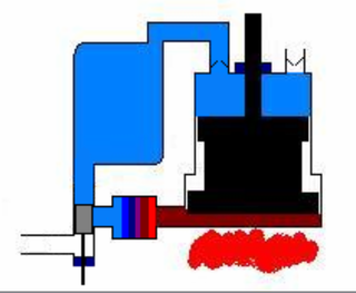
Beta-type Stirling engine, with only one cylinder, hot at one end and cold at the other. A loose-fitting displacer shunts the air between the hot and cold ends of the cylinder. A power piston at the open end of the cylinder drives the flywheel
A beta Stirling has a single power piston arranged within the same cylinder on the same shaft as a displacer piston. The displacer piston is a loose fit and does not extract any power from the expanding gas but only serves to shuttle the working gas between the hot and cold heat exchangers. When the working gas is pushed to the hot end of the cylinder it expands and pushes the power piston. When it is pushed to the cold end of the cylinder it contracts and the momentum of the machine, usually enhanced by a flywheel, pushes the power piston the other way to compress the gas. Unlike the alpha type, the beta type avoids the technical problems of hot moving seals, as the power piston is not in contact with the hot gas.[53]
Power piston (dark grey) has compressed the gas, the displacer piston (light grey) has moved so that most of the gas is adjacent to the hot heat exchanger.
The heated gas increases in pressure and pushes the power piston to the farthest limit of the power stroke.
The displacer piston now moves, shunting the gas to the cold end of the cylinder.
The cooled gas is now compressed by the flywheel momentum. This takes less energy, since its pressure drops when it is cooled.
Other types
Top view of two rotating displacers powering the horizontal piston. Regenerators and radiator removed for clarity
Other Stirling configurations continue to interest engineers and inventors.[citation needed]
The rotary Stirling engine seeks to convert power from the Stirling cycle directly into torque, similar to the rotary combustion engine. No practical engine has yet been built but a number of concepts, models and patents have been produced, such as the Quasiturbine engine.[54]
A hybrid between piston and rotary configuration is a double-acting engine. This design rotates the displacers on either side of the power piston. In addition to giving great design variability in the heat transfer area, this layout eliminates all but one external seal on the output shaft and one internal seal on the piston. Also, both sides can be highly pressurized as they balance against each other.[citation needed]
Another alternative is the Fluidyne engine (or Fluidyne heat pump), which uses hydraulic pistons to implement the Stirling cycle. The work produced by a Fluidyne engine goes into pumping the liquid. In its simplest form, the engine contains a working gas, a liquid, and two non-return valves.[citation needed]
The Ringbom engine concept published in 1907 has no rotary mechanism or linkage for the displacer. This is instead driven by a small auxiliary piston, usually a thick displacer rod, with the movement limited by stops.[55][56]
The engineer Andy Ross invented a two-cylinder Stirling engine (positioned at 0°, not 90°) connected using a special yoke.[57][promotion?]
The Franchot engine is a double-acting engine invented by Charles-Louis-Félix Franchot in the nineteenth century. In a double-acting engine, the pressure of the working fluid acts on both sides of the piston. One of the simplest forms of a double-acting machine, the Franchot engine consists of two pistons and two cylinders, and acts like two separate alpha machines. In the Franchot engine, each piston acts in two gas phases, which makes more efficient use of the mechanical components than a single-acting alpha machine. However, a disadvantage of this machine is that one connecting rod must have a sliding seal at the hot side of the engine, which is difficult when dealing with high pressures and temperatures.[58]
Free-piston engines
Various free-piston Stirling configurations... F. "free cylinder", G. Fluidyne, H. "double-acting" Stirling (typically 4 cylinders).
Free-piston Stirling engines include those with liquid pistons and those with diaphragms as pistons. In a free-piston device, energy may be added or removed by an electrical linear alternator, pump or other coaxial device. This avoids the need for a linkage, and reduces the number of moving parts. In some designs, friction and wear are nearly eliminated by the use of non-contact gas bearings or very precise suspension through planar springs.[citation needed]
Four basic steps in the cycle of a free-piston Stirling engine are:[citation needed]
The power piston is pushed outwards by the expanding gas thus doing work. Gravity plays no role in the cycle.
The gas volume in the engine increases and therefore the pressure reduces, which causes a pressure difference across the displacer rod to force the displacer towards the hot end. When the displacer moves, the piston is almost stationary and therefore the gas volume is almost constant. This step results in the constant volume cooling process, which reduces the pressure of the gas.
The reduced pressure now arrests the outward motion of the piston and it begins to accelerate towards the hot end again and by its own inertia, compresses the now cold gas, which is mainly in the cold space.
As the pressure increases, a point is reached where the pressure differential across the displacer rod becomes large enough to begin to push the displacer rod (and therefore also the displacer) towards the piston and thereby collapsing the cold space and transferring the cold, compressed gas towards the hot side in an almost constant volume process. As the gas arrives in the hot side the pressure increases and begins to move the piston outwards to initiate the expansion step as explained in (1).
In the early 1960s, William T. Beale of Ohio University located in Athens, Ohio, invented a free piston version of the Stirling engine to overcome the difficulty of lubricating the crank mechanism.[59] While the invention of the basic free piston Stirling engine is generally attributed to Beale, independent inventions of similar types of engines were made by E.H. Cooke-Yarborough and C. West at the Harwell Laboratories of the UK AERE.[60] G.M. Benson also made important early contributions and patented many novel free-piston configurations.[61][62]
The first known mention of a Stirling cycle machine using freely moving components is a British patent disclosure in 1876.[63] This machine was envisaged as a refrigerator (i.e., the reversed Stirling cycle). The first consumer product to utilize a free piston Stirling device was a portable refrigerator manufactured by Twinbird Corporation of Japan and offered in the US by Coleman in 2004.[citation needed]
Flat engines
Cutaway of the flat Stirling engine: 10: Hot cylinder. 11: A volume of hot cylinder. 12: B volume of hot cylinder. 17: Warm piston diaphragm. 18: Heating medium. 19: Piston rod. 20: Cold cylinder. 21: A Volume of cold cylinder. 22: B Volume of cold cylinder. 27: Cold piston diaphragm. 28: Coolant medium. 30: Working cylinder. 31: A volume of working cylinder. 32: B volume of working cylinder. 37: Working piston diaphragm. 41: Regenerator mass of A volume. 42: Regenerator mass of B volume. 48: Heat accumulator. 50: Thermal insulation. 60: Generator. 63: Magnetic circuit. 64: Electrical winding. 70: Channel connecting warm and working cylinders.
Design of the flat double-acting Stirling engine solves the drive of a displacer with the help of the fact that areas of the hot and cold pistons of the displacer are different.[citation needed]
The drive does so without any mechanical transmission.[citation needed] Using diaphragms eliminates friction and need for lubricants.[citation needed]
When the displacer is in motion, the generator holds the working piston in the limit position, which brings the engine working cycle close to an ideal Stirling cycle.[citation needed] The ratio of the area of the heat exchangers to the volume of the machine increases by the implementation of a flat design.[citation needed]
Flat design of the working cylinder approximates thermal process of the expansion and compression closer to the isothermal one.[citation needed]
The disadvantage is a large area of the thermal insulation between the hot and cold space.[64]
Thermoacoustic cycle
Thermoacoustic devices are very different from Stirling devices, although the individual path travelled by each working gas molecule does follow a real Stirling cycle. These devices include the thermoacoustic engine and thermoacoustic refrigerator. High-amplitude acoustic standing waves cause compression and expansion analogous to a Stirling power piston, while out-of-phase acoustic travelling waves cause displacement along a temperature gradient, analogous to a Stirling displacer piston. Thus a thermoacoustic device typically does not have a displacer, as found in a beta or gamma Stirling.[citation needed]
Other developments
NASA has considered nuclear-decay heated Stirling Engines for extended missions to the outer solar system.[65] In 2018, NASA and the United States Department of Energy announced that they had successfully tested a new type of nuclear reactor called KRUSTY, which stands for "Kilopower Reactor Using Stirling TechnologY", and which is designed to be able to power deep space vehicles and probes as well as exoplanetary encampments.[66]
At the 2012 Cable-Tec Expo put on by the Society of Cable Telecommunications Engineers, Dean Kamen took the stage with Time Warner Cable Chief Technology Officer Mike LaJoie to announce a new initiative between his company Deka Research and the SCTE. Kamen refers to it as a Stirling engine.[67][68]
Operational considerations
Video showing the compressor and displacer of a very small Stirling Engine in action
Size and temperature
Very low-power engines have been built that run on a temperature difference of as little as 0.5 K.[69] A displacer-type Stirling engine has one piston and one displacer. A temperature difference is required between the top and bottom of the large cylinder to run the engine. In the case of the low-temperature-difference (LTD) Stirling engine, the temperature difference between one's hand and the surrounding air can be enough to run the engine.[70] The power piston in the displacer-type Stirling engine is tightly sealed and is controlled to move up and down as the gas inside expands. The displacer, on the other hand, is very loosely fitted so that air can move freely between the hot and cold sections of the engine as the piston moves up and down. The displacer moves up and down to cause most of the gas in the displacer cylinder to be either heated, or cooled.[citation needed]
Stirling engines, especially those that run on small temperature differentials, are quite large for the amount of power that they produce (i.e., they have low specific power). This is primarily due to the heat transfer coefficient of gaseous convection, which limits the heat flux that can be attained in a typical cold heat exchanger to about 500W/(m2·K), and in a hot heat exchanger to about 500–5000W/(m2·K).[71] Compared with internal combustion engines, this makes it more challenging for the engine designer to transfer heat into and out of the working gas. Because of the thermal efficiency the required heat transfer grows with lower temperature difference, and the heat exchanger surface (and cost) for 1kW output grows with (1/ΔT)2. Therefore, the specific cost of very low temperature difference engines is very high. Increasing the temperature differential and/or pressure allows Stirling engines to produce more power, assuming the heat exchangers are designed for the increased heat load, and can deliver the convected heat flux necessary.
A Stirling engine cannot start instantly; it literally needs to "warm up". This is true of all external combustion engines, but the warm up time may be longer for Stirlings than for others of this type such as steam engines. Stirling engines are best used as constant speed engines.
Power output of a Stirling tends to be constant and to adjust it can sometimes require careful design and additional mechanisms. Typically, changes in output are achieved by varying the displacement of the engine (often through use of a swashplatecrankshaft arrangement), or by changing the quantity of working fluid, or by altering the piston/displacer phase angle, or in some cases simply by altering the engine load. This property is less of a drawback in hybrid electric propulsion or "base load" utility generation where constant power output is actually desirable.
Gas choice
Video of a bench top stirling engine demonstrating the speed and power.
The gas used should have a low heat capacity, so that a given amount of transferred heat leads to a large increase in pressure. Considering this issue, helium would be the best gas because of its very low heat capacity. Air is a viable working fluid,[72] but the oxygen in a highly pressurized air engine can cause fatal accidents caused by lubricating oil explosions.[73] Following one such accident Philips pioneered the use of other gases to avoid such risk of explosions.
Hydrogen's low viscosity and high thermal conductivity make it the most powerful working gas, primarily because the engine can run faster than with other gases. However, because of hydrogen absorption, and given the high diffusion rate associated with this low molecular weight gas, particularly at high temperatures, H2 leaks through the solid metal of the heater. Diffusion through carbon steel is too high to be practical, but may be acceptably low for metals such as aluminum, or even stainless steel. Certain ceramics also greatly reduce diffusion. Hermetic pressure vessel seals are necessary to maintain pressure inside the engine without replacement of lost gas. For high-temperature-differential (HTD) engines, auxiliary systems may be required to maintain high-pressure working fluid. These systems can be a gas storage bottle or a gas generator. Hydrogen can be generated by electrolysis of water, the action of steam on red hot carbon-based fuel, by gasification of hydrocarbon fuel, or by the reaction of acid on metal. Hydrogen can also cause the embrittlement of metals. Hydrogen is a flammable gas, which is a safety concern if released from the engine.
Most technically advanced Stirling engines, like those developed for United States government labs, use helium as the working gas, because it functions close to the efficiency and power density of hydrogen with fewer of the material containment issues. Helium is inert, and hence not flammable. Helium is relatively expensive, and must be supplied as bottled gas. One test showed hydrogen to be 5% (absolute) more efficient than helium (24% relatively) in the GPU-3 Stirling engine.[74] The researcher Allan Organ demonstrated that a well-designed air engine is theoretically just as efficient as a helium or hydrogen engine, but helium and hydrogen engines are several times more powerful per unit volume.
Some engines use air or nitrogen as the working fluid. These gases have much lower power density (which increases engine costs), but they are more convenient to use and they minimize the problems of gas containment and supply (which decreases costs). The use of compressed air in contact with flammable materials or substances such as lubricating oil introduces an explosion hazard, because compressed air contains a high partial pressure of oxygen. However, oxygen can be removed from air through an oxidation reaction or bottled nitrogen can be used, which is nearly inert and very safe.
Other possible lighter-than-air gases include methane and ammonia.
Pressurization
In most high-power Stirling engines, both the minimum pressure and mean pressure of the working fluid are above atmospheric pressure. This initial engine pressurization can be realized by a pump, or by filling the engine from a compressed gas tank, or even just by sealing the engine when the mean temperature is lower than the mean operating temperature. All of these methods increase the mass of working fluid in the thermodynamic cycle. All of the heat exchangers must be sized appropriately to supply the necessary heat transfer rates. If the heat exchangers are well designed and can supply the heat flux needed for convective heat transfer, then the engine, in a first approximation, produces power in proportion to the mean pressure, as predicted by the West number and Beale number. In practice, the maximum pressure is also limited to the safe pressure of the pressure vessel. Like most aspects of Stirling engine design, optimization is multivariate, and often has conflicting requirements.[71] A difficulty of pressurization is that while it improves the power, the heat required increases proportionately to the increased power. This heat transfer is made increasingly difficult with pressurization since increased pressure also demands increased thicknesses of the walls of the engine, which, in turn, increase the resistance to heat transfer.[citation needed]
Lubricants and friction
A modern Stirling engine and generator set with 55 kW electrical output, for combined heat and power applications.
At high temperatures and pressures, the oxygen in air-pressurized crankcases, or in the working gas of hot air engines, can combine with the engine's lubricating oil and explode. At least one person has died in such an explosion.[73] Lubricants can also clog heat exchangers, especially the regenerator. For these reasons, designers prefer non-lubricated, low-coefficient of friction materials (such as rulon or graphite), with low normal forces on the moving parts, especially for sliding seals. Some designs avoid sliding surfaces altogether by using diaphragms for sealed pistons. These are some of the factors that allow Stirling engines to have lower maintenance requirements and longer life than internal-combustion engines.[citation needed]
Theoretical thermal efficiency equals that of the ideal Carnot cycle, i.e. the highest efficiency attainable by any heat engine. However, though it is useful for illustrating general principles, practical Stirling engines deviate substantially from the ideal.[75] It has been argued that its indiscriminate use in many standard books on engineering thermodynamics has done a disservice to the study of Stirling engines in general.[76][77]
Stirling engines cannot achieve total efficiencies typical of an internal combustion engine, the main constraint being thermal efficiency. During internal combustion, temperatures achieve around 1500°C–1600°C for a short period of time, resulting in greater mean heat supply temperature of the thermodynamic cycle than any Stirling engine could achieve. It is not possible to supply heat at temperatures that high by conduction, as it is done in Stirling engines because no material could conduct heat from combustion in that high temperature without huge heat losses and problems related to heat deformation of materials.[citation needed]
Stirling engines are capable of quiet operation and can use almost any heat source. The heat energy source is generated external to the Stirling engine rather than by internal combustion as with the Otto cycle or Diesel cycle engines. This type of engine is currently generating interest as the core component of micro combined heat and power (CHP) units, in which it is more efficient and safer than a comparable steam engine.[78][79] However, it has a low power-to-weight ratio,[80] rendering it more suitable for use in static installations where space and weight are not at a premium.[citation needed]
Other real-world issues reduce the efficiency of actual engines, due to the limits of convective heat transfer and viscous flow (friction). There are also practical, mechanical considerations: for instance, a simple kinematic linkage may be favoured over a more complex mechanism needed to replicate the idealized cycle, and limitations imposed by available materials such as non-ideal properties of the working gas, thermal conductivity, tensile strength, creep, rupture strength, and melting point. A question that often arises is whether the ideal cycle with isothermal expansion and compression is in fact the correct ideal cycle to apply to the Stirling engine. Professor C. J. Rallis has pointed out that it is very difficult to imagine any condition where the expansion and compression spaces may approach isothermal behavior and it is far more realistic to imagine these spaces as adiabatic.[81] An ideal analysis where the expansion and compression spaces are taken to be adiabatic with isothermal heat exchangers and perfect regeneration was analyzed by Rallis and presented as a better ideal yardstick for Stirling machinery. He called this cycle the 'pseudo-Stirling cycle' or 'ideal adiabatic Stirling cycle'. An important consequence of this ideal cycle is that it does not predict Carnot efficiency. A further conclusion of this ideal cycle is that maximum efficiencies are found at lower compression ratios, a characteristic observed in real machines. In an independent work, T. Finkelstein also assumed adiabatic expansion and compression spaces in his analysis of Stirling machinery[82]
The ideal Stirling cycle is unattainable in the real world, as with any heat engine. The efficiency of Stirling machines is also linked to the environmental temperature: higher efficiency is obtained when the weather is cooler, thus making this type of engine less attractive in places with warmer climates. As with other external combustion engines, Stirling engines can use heat sources other than the combustion of fuels. For example, various designs for solar-powered Stirling engines have been developed.
Comparison with internal combustion engines
This article contains a pro and con list. Please help rewriting it into consolidated sections based on topics.(May 2021)
In contrast to internal combustion engines, Stirling engines have the potential to use renewable heat sources more easily, and to be quieter and more reliable with lower maintenance. They are preferred for applications that value these unique advantages, particularly if the cost per unit energy generated is more important than the capital cost per unit power. On this basis, Stirling engines are cost-competitive up to about 100kW.[83]
Compared to an internal combustion engine of the same power rating, Stirling engines currently have a higher capital cost and are usually larger and heavier. However, they are more efficient than most internal combustion engines.[84] Their lower maintenance requirements make the overall energy cost comparable. The thermal efficiency is also comparable (for small engines), ranging from 15% to 30%.[83] For applications such as micro-CHP, a Stirling engine is often preferable to an internal combustion engine. Other applications include water pumping, astronautics, and electrical generation from plentiful energy sources that are incompatible with the internal combustion engine, such as solar energy, and biomass such as agricultural waste and other waste such as domestic refuse. However, Stirling engines are generally not price-competitive as an automobile engine, because of high cost per unit power, & low power density.[citation needed]
Basic analysis is based on the closed-form Schmidt analysis.[85][86]
Advantages of Stirling engines compared to internal combustion engines include:
Stirling engines can run directly on any available heat source, not just one produced by combustion, so they can run on heat from solar, geothermal, biological, nuclear sources or waste heat from industrial processes.
A continuous combustion process can be used to supply heat, so those emissions associated with the intermittent combustion processes of a reciprocating internal combustion engine can be reduced.
Some types of Stirling engines have the bearings and seals on the cool side of the engine, where they require less lubricant and last longer than equivalents on other reciprocating engine types.
The engine mechanisms are in some ways simpler than other reciprocating engine types. No valves are needed, and the burner system can be relatively simple. Crude Stirling engines can be made using common household materials.[87]
A Stirling engine uses a single-phase working fluid that maintains an internal pressure close to the design pressure, and thus for a properly designed system the risk of explosion is low. In comparison, a steam engine uses a two-phase gas/liquid working fluid, so a faulty overpressure relief valve can cause an explosion.
In some cases, low operating pressure allows the use of lightweight cylinders.
They can be built to run quietly and without an air supply, for air-independent propulsion use in submarines.
They start easily (albeit slowly, after warmup) and run more efficiently in cold weather, in contrast to the internal combustion, which starts quickly in warm weather, but not in cold weather.
A Stirling engine used for pumping water can be configured so that the water cools the compression space. This increases efficiency when pumping cold water.
They are extremely flexible. They can be used as CHP (combined heat and power) in the winter and as coolers in summer.
Waste heat is easily harvested (compared to waste heat from an internal combustion engine), making Stirling engines useful for dual-output heat and power systems.
In 1986 NASA built a Stirling automotive engine and installed it in a Chevrolet Celebrity. Fuel economy was improved 45% and emissions were greatly reduced. Acceleration (power response) was equivalent to the standard internal combustion engine. This engine, designated the Mod II, also nullifies arguments that Stirling engines are heavy, expensive, unreliable, and demonstrate poor performance.[88] A catalytic converter, muffler and frequent oil changes are not required.[88]
Disadvantages of Stirling engines compared to internal combustion engines include:
Stirling engine designs require heat exchangers for heat input and for heat output, and these must contain the pressure of the working fluid, where the pressure is proportional to the engine power output. In addition, the expansion-side heat exchanger is often at very high temperature, so the materials must resist the corrosive effects of the heat source, and have low creep. Typically these material requirements substantially increase the cost of the engine. The materials and assembly costs for a high-temperature heat exchanger typically accounts for 40% of the total engine cost.[73]
All thermodynamic cycles require large temperature differentials for efficient operation. In an external combustion engine, the heater temperature always equals or exceeds the expansion temperature. This means that the metallurgical requirements for the heater material are very demanding. This is similar to a Gas turbine, but is in contrast to an Otto engine or Diesel engine, where the expansion temperature can far exceed the metallurgical limit of the engine materials, because the input heat source is not conducted through the engine, so engine materials operate closer to the average temperature of the working gas. The Stirling cycle is not actually achievable; the real cycle in Stirling machines is less efficient than the theoretical Stirling cycle. The efficiency of the Stirling cycle is lower where the ambient temperatures are mild, while it would give its best results in a cool environment, such as northern countries' winters.
Dissipation of waste heat is especially complicated because the coolant temperature is kept as low as possible to maximize thermal efficiency. This increases the size of the radiators, which can make packaging difficult. Along with materials cost, this has been one of the factors limiting the adoption of Stirling engines as automotive prime movers. For other applications such as ship propulsion and stationary microgeneration systems using combined heat and power (CHP) high power density is not required.[40]
Applications of the Stirling engine range from heating and cooling to underwater power systems. A Stirling engine can function in reverse as a heat pump for heating or cooling. Other uses include combined heat and power, solar power generation, Stirling cryocoolers, heat pump, marine engines, low power model aircraft engines,[89] and low temperature difference engines.
↑ "Stirling Engines", G. Walker (1980), Clarendon Press, Oxford, page 1: "A Stirling engine is a mechanical device which operates on a *closed* regenerative thermodynamic cycle, with cyclic compression and expansion of the working fluid at different temperature levels."
↑ English patent 4081 of 1816 Improvements for diminishing the consumption of fuel and in particular an engine capable of being applied to the moving (of) machinery on a principle entirely new. as reproduced in part in C.M. Hargreaves (1991), Appendix B, with full transcription of text in R. Sier (1995), p.[pageneeded]
1 2 "Power from the people". BBC News. 31 October 2003. Archived from the original on 1 November 2003. The boiler is based on the Stirling engine, dreamed up by the Scottish inventor Robert Stirling in 1816. [...] The technical name given to this particular use is Micro Combined Heat and Power or Micro CHP.
↑ Formosa, Fabien; Fréchette, Luc G. (1 August 2013). "Scaling laws for free piston Stirling engine design: Benefits and challenges of miniaturization". Energy. 57: 796–808. Bibcode:2013Ene....57..796F. doi:10.1016/j.energy.2013.05.009.
↑ Dudek, Jerzy; Klimek, Piotr; Kołodziejak, Grzegorz; Niemczewska, Joanna; Zaleska-Bartosz, Joanna (2010). "Landfill Gas Energy Technologies"(PDF). Global Methane Initiative. Instytut Nafty i Gazu / US Environmental Protection Agency. Archived(PDF) from the original on 25 July 2015. Retrieved 24 July 2015.
↑ H.W. Brandhorst; J.A. Rodiek (2005). "A 25 kW Solar Stirling Concept for Lunar Surface Exploration"(PDF). In International Astronautics Federation (ed.). Proceedings of the 56th International Astronautical Congress. IAC-05-C3.P.05. Archived from the original(PDF) on 7 January 2012. Retrieved 18 March 2012.
↑ B. Kongtragool; S. Wongwises (2003). "A review of solar-powered Stirling engines and low temperature differential Stirling engines". Renewable and Sustainable Energy Reviews. 7 (2): 131–154. doi:10.1016/S1364-0321(02)00053-9.
↑ "Ringbom Stirling Engines", James R. Senft, 1993, Oxford University Press
↑ Ossian Ringbom (of Borgå, Finland) "Hot-air engine"Archived 17 October 2015 at the Wayback Machine U.S. Patent no. 856,102 (filed: 17 July 1905; issued: 4 June 1907).
↑ Rallis C. J., Urieli I. and Berchowitz D.M. A New Ported Constant Volume External Heat Supply Regenerative Cycle, 12th IECEC, Washington DC, 1977, pp 1534–1537.
↑ Finkelstein, T. Generalized Thermodynamic Analysis of Stirling Engines. Paper 118B, Society of Automotive Engineers, 1960.
↑ Mcconaghy, Robert (1986). "Design of a Stirling Engine for Model Aircraft". IECEC: 490–493.
General and cited references
E.H. Cooke-Yarborough; E. Franklin; J. Geisow; R. Howlett; C.D. West (1974). "Harwell Thermo-Mechanical Generator". Proceedings of the 9th IECEC. San Francisco: American Society of Mechanical Engineers. pp.1132–1136. Bibcode:1974iece.conf.1132C.
E.H. Cooke-Yarborough (1970). "Heat Engines", US patent 3548589. Granted to Atomic Energy Authority UK, 22 December 1970.
E.H. Cooke-Yarborough (1967). "A Proposal for a Heat-Powered Nonrotating Electrical Alternator", Harwell Memorandum AERE-M881.
T. Finkelstein; A.J. Organ (2001). Air Engines. Professional Engineering Publishing. ISBN1-86058-338-5.
A.J. Organ (1992). Thermodynamics and Gas Dynamics of the Stirling Cycle Machine. Cambridge University Press. ISBN0-521-41363-X.
R. Sier (1995). Reverend Robert Stirling D.D: A Biography of the Inventor of the Heat Economiser and Stirling Cycle Engine. L.A Mair. ISBN0-9526417-0-4.
R.C. Belaire (1977). "Device for decreasing the start-up time for stirling engines", US patent 4057962. Granted to Ford Motor Company, 15 November 1977.
J. Harrison (2008). "What is micro generation?". Claverton Energy Research Group. Retrieved 19 January 2009.
P.H. Ceperley (1979). "A pistonless Stirling engine—The traveling wave heat engine". Journal of the Acoustical Society of America. 66 (5): 1508–1513. Bibcode:1979ASAJ...66.1508C. doi:10.1121/1.383505.
Lund University, Department of Energy Science: Division of Combustion Engines. "Stirling Engine Research". Archived from the original on 19 April 2008. Retrieved 19 January 2009.
A Carnot heat engine is a theoretical heat engine that operates on the Carnot cycle. The basic model for this engine was developed by Nicolas Léonard Sadi Carnot in 1824. The Carnot engine model was graphically expanded by Benoît Paul Émile Clapeyron in 1834 and mathematically explored by Rudolf Clausius in 1857, work that led to the fundamental thermodynamic concept of entropy. The Carnot engine is the most efficient heat engine which is theoretically possible. The efficiency depends only upon the absolute temperatures of the hot and cold heat reservoirs between which it operates.
An engine or motor is a machine designed to convert one or more forms of energy into mechanical energy.
A heat engine is a system that converts heat to usable energy, particularly mechanical energy, which can then be used to do mechanical work. While originally conceived in the context of mechanical energy, the concept of the heat engine has been applied to various other kinds of energy, particularly electrical, since at least the late 19th century. The heat engine does this by bringing a working substance from a higher state temperature to a lower state temperature. A heat source generates thermal energy that brings the working substance to the higher temperature state. The working substance generates work in the working body of the engine while transferring heat to the colder sink until it reaches a lower temperature state. During this process some of the thermal energy is converted into work by exploiting the properties of the working substance. The working substance can be any system with a non-zero heat capacity, but it usually is a gas or liquid. During this process, some heat is normally lost to the surroundings and is not converted to work. Also, some energy is unusable because of friction and drag.
A reciprocating engine, also often known as a piston engine, is typically a heat engine that uses one or more reciprocating pistons to convert high temperature and high pressure into a rotating motion. This article describes the common features of all types. The main types are: the internal combustion engine, used extensively in motor vehicles; the steam engine, the mainstay of the Industrial Revolution; and the Stirling engine for niche applications. Internal combustion engines are further classified in two ways: either a spark-ignition (SI) engine, where the spark plug initiates the combustion; or a compression-ignition (CI) engine, where the air within the cylinder is compressed, thus heating it, so that the heated air ignites fuel that is injected then or earlier.
A steam engine is a heat engine that performs mechanical work using steam as its working fluid. The steam engine uses the force produced by steam pressure to push a piston back and forth inside a cylinder. This pushing force can be transformed, by a connecting rod and crank, into rotational force for work. The term "steam engine" is most commonly applied to reciprocating engines as just described, although some authorities have also referred to the steam turbine and devices such as Hero's aeolipile as "steam engines". The essential feature of steam engines is that they are external combustion engines, where the working fluid is separated from the combustion products. The ideal thermodynamic cycle used to analyze this process is called the Rankine cycle. In general usage, the term steam engine can refer to either complete steam plants, such as railway steam locomotives and portable engines, or may refer to the piston or turbine machinery alone, as in the beam engine and stationary steam engine.
The Stirling cycle is a thermodynamic cycle that describes the general class of Stirling devices. This includes the original Stirling engine that was invented, developed and patented in 1816 by Robert Stirling with help from his brother, an engineer.
The Brayton cycle, also known as the Joule cycle, is a thermodynamic cycle that describes the operation of certain heat engines that have air or some other gas as their working fluid. It is characterized by isentropic compression and expansion, and isobaric heat addition and rejection, though practical engines have adiabatic rather than isentropic steps.
A combined cycle power plant is an assembly of heat engines that work in tandem from the same source of heat, converting it into mechanical energy. On land, when used to make electricity the most common type is called a combined cycle gas turbine (CCGT) plant, which is a kind of gas-fired power plant. The same principle is also used for marine propulsion, where it is called a combined gas and steam (COGAS) plant. Combining two or more thermodynamic cycles improves overall efficiency, which reduces fuel costs.
A refrigerator designed to reach cryogenic temperatures is often called a cryocooler. The term is most often used for smaller systems, typically table-top size, with input powers less than about 20 kW. Some can have input powers as low as 2–3 W. Large systems, such as those used for cooling the superconducting magnets in particle accelerators are more often called cryogenic refrigerators. Their input powers can be as high as 1 MW. In most cases cryocoolers use a cryogenic fluid as the working substance and employ moving parts to cycle the fluid around a thermodynamic cycle. The fluid is typically compressed at room temperature, precooled in a heat exchanger, then expanded at some low temperature. The returning low-pressure fluid passes through the heat exchanger to precool the high-pressure fluid before entering the compressor intake. The cycle is then repeated.
The Ericsson cycle is named after inventor John Ericsson who designed and built many unique heat engines based on various thermodynamic cycles. He is credited with inventing two unique heat engine cycles and developing practical engines based on these cycles. His first cycle is now known as the closed Brayton cycle, while his second cycle is what is now called the Ericsson cycle. Ericsson is one of the few who built open-cycle engines, but he also built closed-cycle ones.
A hot air engine is any heat engine that uses the expansion and contraction of air under the influence of a temperature change to convert thermal energy into mechanical work. These engines may be based on a number of thermodynamic cycles encompassing both open cycle devices such as those of Sir George Cayley and John Ericsson and the closed cycle engine of Robert Stirling. Hot air engines are distinct from the better known internal combustion based engine and steam engine.
This timeline of heat engine technology describes how heat engines have been known since antiquity but have been made into increasingly useful devices since the 17th century as a better understanding of the processes involved was gained. A heat engine is any system that converts heat to mechanical energy, which can then be used to do mechanical work.They continue to be developed today.
Economizers, or economisers (UK), are mechanical devices intended to reduce energy consumption, or to perform useful function such as preheating a fluid. The term economizer is used for other purposes as well. Boiler, power plant, heating, refrigeration, ventilating, and air conditioning (HVAC) uses are discussed in this article. In simple terms, an economizer is a heat exchanger.
The hot-bulb engine, also known as a semi-diesel, is a type of internal combustion engine in which fuel ignites by coming in contact with a red-hot metal surface inside a bulb, followed by the introduction of air (oxygen) compressed into the hot-bulb chamber by the rising piston. There is some ignition when the fuel is introduced, but it quickly uses up the available oxygen in the bulb. Vigorous ignition takes place only when sufficient oxygen is supplied to the hot-bulb chamber on the compression stroke of the engine.
Engine efficiency of thermal engines is the relationship between the total energy contained in the fuel, and the amount of energy used to perform useful work. There are two classifications of thermal engines-
Internal combustion and
External combustion engines.
The term six-stroke engine has been applied to a number of alternative internal combustion engine designs that attempt to improve on traditional two-stroke and four-stroke engines. Claimed advantages may include increased fuel efficiency, reduced mechanical complexity, and/or reduced emissions. These engines can be divided into two groups based on the number of pistons that contribute to the six strokes.
A regenerative heat exchanger, or more commonly a regenerator, is a type of heat exchanger where heat from the hot fluid is intermittently stored in a thermal storage medium before it is transferred to the cold fluid. To accomplish this the hot fluid is brought into contact with the heat storage medium, then the fluid is displaced with the cold fluid, which absorbs the heat.
The US Rider-Ericsson Engine Company was the successor of the DeLamater Iron Works and the Rider Engine Company, having bought from both companies their extensive plants and entire stocks of engines and patterns, covering all styles of Rider and Ericsson hot air pumping engines brought out by both of the old companies since 1844, excepting the original Ericsson engine, the patterns of which were burned in the DeLameter fire of 1888.
A liquid nitrogen engine is powered by liquid nitrogen, which is stored in a tank. Traditional nitrogen engine designs work by heating the liquid nitrogen in a heat exchanger, extracting heat from the ambient air and using the resulting pressurized gas to operate a piston or rotary motor. Vehicles propelled by liquid nitrogen have been demonstrated, but are not used commercially. One such vehicle, Liquid Air, was demonstrated in 1902.
An internal combustion engine is a heat engine in which the combustion of a fuel occurs with an oxidizer in a combustion chamber that is an integral part of the working fluid flow circuit. In an internal combustion engine, the expansion of the high-temperature and high-pressure gases produced by combustion applies direct force to some component of the engine. The force is typically applied to pistons, turbine blades, a rotor, or a nozzle. This force moves the component over a distance, transforming chemical energy into kinetic energy which is used to propel, move or power whatever the engine is attached to.
This page is based on this Wikipedia article Text is available under the CC BY-SA 4.0 license; additional terms may apply. Images, videos and audio are available under their respective licenses.