Electromagnetic induction

Last updated

Alternating electric current flows through the solenoid on the left, producing a changing magnetic field. This field causes, by electromagnetic induction, an electric current to flow in the wire loop on the right. Electromagnetic induction - solenoid to loop - animation.gif
Alternating electric current flows through the solenoid on the left, producing a changing magnetic field. This field causes, by electromagnetic induction, an electric current to flow in the wire loop on the right.

Electromagnetic or magnetic induction is the production of an electromotive force (emf) across an electrical conductor in a changing magnetic field.

Contents

Michael Faraday is generally credited with the discovery of induction in 1831, and James Clerk Maxwell mathematically described it as Faraday's law of induction. Lenz's law describes the direction of the induced field. Faraday's law was later generalized to become the Maxwell–Faraday equation, one of the four Maxwell equations in his theory of electromagnetism.

Electromagnetic induction has found many applications, including electrical components such as inductors and transformers, and devices such as electric motors and generators.

History

Faraday's experiment showing induction between coils of wire: The liquid battery (right) provides a current that flows through the small coil (A), creating a magnetic field. When the coils are stationary, no current is induced. But when the small coil is moved in or out of the large coil (B), the magnetic flux through the large coil changes, inducing a current which is detected by the galvanometer (G). Induction experiment.png
Faraday's experiment showing induction between coils of wire: The liquid battery (right) provides a current that flows through the small coil (A), creating a magnetic field. When the coils are stationary, no current is induced. But when the small coil is moved in or out of the large coil (B), the magnetic flux through the large coil changes, inducing a current which is detected by the galvanometer (G).
A diagram of Faraday's iron ring apparatus. Change in the magnetic flux of the left coil induces a current in the right coil. Faraday emf experiment.svg
A diagram of Faraday's iron ring apparatus. Change in the magnetic flux of the left coil induces a current in the right coil.

Electromagnetic induction was discovered by Michael Faraday, published in 1831. [3] [4] It was discovered independently by Joseph Henry in 1832. [5] [6]

In Faraday's first experimental demonstration (August 29, 1831), he wrapped two wires around opposite sides of an iron ring or "torus" (an arrangement similar to a modern toroidal transformer).[ citation needed ] Based on his understanding of electromagnets, he expected that, when current started to flow in one wire, a sort of wave would travel through the ring and cause some electrical effect on the opposite side. He plugged one wire into a galvanometer, and watched it as he connected the other wire to a battery. He saw a transient current, which he called a "wave of electricity", when he connected the wire to the battery and another when he disconnected it. [7] This induction was due to the change in magnetic flux that occurred when the battery was connected and disconnected. [2] Within two months, Faraday found several other manifestations of electromagnetic induction. For example, he saw transient currents when he quickly slid a bar magnet in and out of a coil of wires, and he generated a steady (DC) current by rotating a copper disk near the bar magnet with a sliding electrical lead ("Faraday's disk"). [8]

Faraday explained electromagnetic induction using a concept he called lines of force. However, scientists at the time widely rejected his theoretical ideas, mainly because they were not formulated mathematically. [9] An exception was James Clerk Maxwell, who used Faraday's ideas as the basis of his quantitative electromagnetic theory. [9] [10] [11] In Maxwell's model, the time varying aspect of electromagnetic induction is expressed as a differential equation, which Oliver Heaviside referred to as Faraday's law even though it is slightly different from Faraday's original formulation and does not describe motional emf. Heaviside's version (see Maxwell–Faraday equation below) is the form recognized today in the group of equations known as Maxwell's equations.

In 1834 Heinrich Lenz formulated the law named after him to describe the "flux through the circuit". Lenz's law gives the direction of the induced emf and current resulting from electromagnetic induction.

Theory

Faraday's law of induction and Lenz's law

A solenoid Solenoid-1.png
A solenoid
The longitudinal cross section of a solenoid with a constant electrical current running through it. The magnetic field lines are indicated, with their direction shown by arrows. The magnetic flux corresponds to the 'density of field lines'. The magnetic flux is thus densest in the middle of the solenoid, and weakest outside of it. VFPt Solenoid correct2.svg
The longitudinal cross section of a solenoid with a constant electrical current running through it. The magnetic field lines are indicated, with their direction shown by arrows. The magnetic flux corresponds to the 'density of field lines'. The magnetic flux is thus densest in the middle of the solenoid, and weakest outside of it.

Faraday's law of induction makes use of the magnetic flux ΦB through a region of space enclosed by a wire loop. The magnetic flux is defined by a surface integral: [12]

where dA is an element of the surface Σ enclosed by the wire loop, B is the magnetic field. The dot product B·dA corresponds to an infinitesimal amount of magnetic flux. In more visual terms, the magnetic flux through the wire loop is proportional to the number of magnetic field lines that pass through the loop.

When the flux through the surface changes, Faraday's law of induction says that the wire loop acquires an electromotive force (emf). [note 1] The most widespread version of this law states that the induced electromotive force in any closed circuit is equal to the rate of change of the magnetic flux enclosed by the circuit: [16] [17]

where is the emf and ΦB is the magnetic flux. The direction of the electromotive force is given by Lenz's law which states that an induced current will flow in the direction that will oppose the change which produced it. [18] This is due to the negative sign in the previous equation. To increase the generated emf, a common approach is to exploit flux linkage by creating a tightly wound coil of wire, composed of N identical turns, each with the same magnetic flux going through them. The resulting emf is then N times that of one single wire. [19] [20]

Generating an emf through a variation of the magnetic flux through the surface of a wire loop can be achieved in several ways:

  1. the magnetic field B changes (e.g. an alternating magnetic field, or moving a wire loop towards a bar magnet where the B field is stronger),
  2. the wire loop is deformed and the surface Σ changes,
  3. the orientation of the surface dA changes (e.g. spinning a wire loop into a fixed magnetic field),
  4. any combination of the above

Maxwell–Faraday equation

In general, the relation between the emf in a wire loop encircling a surface Σ, and the electric field E in the wire is given by

where d is an element of contour of the surface Σ, combining this with the definition of flux

we can write the integral form of the Maxwell–Faraday equation

It is one of the four Maxwell's equations, and therefore plays a fundamental role in the theory of classical electromagnetism.

Faraday's law and relativity

Faraday's law describes two different phenomena: the motional emf generated by a magnetic force on a moving wire (see Lorentz force), and the transformer emf that is generated by an electric force due to a changing magnetic field (due to the differential form of the Maxwell–Faraday equation). James Clerk Maxwell drew attention to the separate physical phenomena in 1861. [21] [22] This is believed to be a unique example in physics of where such a fundamental law is invoked to explain two such different phenomena. [23]

Albert Einstein noticed that the two situations both corresponded to a relative movement between a conductor and a magnet, and the outcome was unaffected by which one was moving. This was one of the principal paths that led him to develop special relativity. [24]

Applications

The principles of electromagnetic induction are applied in many devices and systems, including:

Electrical generator

Rectangular wire loop rotating at angular velocity o in radially outward pointing magnetic field B of fixed magnitude. The circuit is completed by brushes making sliding contact with top and bottom discs, which have conducting rims. This is a simplified version of the drum generator. Spindle.PNG
Rectangular wire loop rotating at angular velocity ω in radially outward pointing magnetic field B of fixed magnitude. The circuit is completed by brushes making sliding contact with top and bottom discs, which have conducting rims. This is a simplified version of the drum generator.

The emf generated by Faraday's law of induction due to relative movement of a circuit and a magnetic field is the phenomenon underlying electrical generators. When a permanent magnet is moved relative to a conductor, or vice versa, an electromotive force is created. If the wire is connected through an electrical load, current will flow, and thus electrical energy is generated, converting the mechanical energy of motion to electrical energy. For example, the drum generator is based upon the figure to the bottom-right. A different implementation of this idea is the Faraday's disc, shown in simplified form on the right.

In the Faraday's disc example, the disc is rotated in a uniform magnetic field perpendicular to the disc, causing a current to flow in the radial arm due to the Lorentz force. Mechanical work is necessary to drive this current. When the generated current flows through the conducting rim, a magnetic field is generated by this current through Ampère's circuital law (labelled "induced B" in the figure). The rim thus becomes an electromagnet that resists rotation of the disc (an example of Lenz's law). On the far side of the figure, the return current flows from the rotating arm through the far side of the rim to the bottom brush. The B-field induced by this return current opposes the applied B-field, tending to decrease the flux through that side of the circuit, opposing the increase in flux due to rotation. On the near side of the figure, the return current flows from the rotating arm through the near side of the rim to the bottom brush. The induced B-field increases the flux on this side of the circuit, opposing the decrease in flux due to r the rotation. The energy required to keep the disc moving, despite this reactive force, is exactly equal to the electrical energy generated (plus energy wasted due to friction, Joule heating, and other inefficiencies). This behavior is common to all generators converting mechanical energy to electrical energy.

Electrical transformer

When the electric current in a loop of wire changes, the changing current creates a changing magnetic field. A second wire in reach of this magnetic field will experience this change in magnetic field as a change in its coupled magnetic flux, . Therefore, an electromotive force is set up in the second loop called the induced emf or transformer emf. If the two ends of this loop are connected through an electrical load, current will flow.

Current clamp

A current clamp Current Clamp.jpg
A current clamp

A current clamp is a type of transformer with a split core which can be spread apart and clipped onto a wire or coil to either measure the current in it or, in reverse, to induce a voltage. Unlike conventional instruments the clamp does not make electrical contact with the conductor or require it to be disconnected during attachment of the clamp.

Magnetic flow meter

Faraday's law is used for measuring the flow of electrically conductive liquids and slurries. Such instruments are called magnetic flow meters. The induced voltage ε generated in the magnetic field B due to a conductive liquid moving at velocity v is thus given by:

where ℓ is the distance between electrodes in the magnetic flow meter.

Eddy currents

Electrical conductors moving through a steady magnetic field, or stationary conductors within a changing magnetic field, will have circular currents induced within them by induction, called eddy currents. Eddy currents flow in closed loops in planes perpendicular to the magnetic field. They have useful applications in eddy current brakes and induction heating systems. However eddy currents induced in the metal magnetic cores of transformers and AC motors and generators are undesirable since they dissipate energy (called core losses) as heat in the resistance of the metal. Cores for these devices use a number of methods to reduce eddy currents:

Electromagnet laminations

Hawkins Electrical Guide - Figure 292 - Eddy currents in a solid armature.jpg

Eddy currents occur when a solid metallic mass is rotated in a magnetic field, because the outer portion of the metal cuts more magnetic lines of force than the inner portion; hence the induced electromotive force is not uniform; this tends to cause electric currents between the points of greatest and least potential. Eddy currents consume a considerable amount of energy and often cause a harmful rise in temperature. [25]

Hawkins Electrical Guide - Figure 293 - Armature core with a few laminations showing effect on eddy currents.jpg

Only five laminations or plates are shown in this example, so as to show the subdivision of the eddy currents. In practical use, the number of laminations or punchings ranges from 40 to 66 per inch (16 to 26 per centimetre), and brings the eddy current loss down to about one percent. While the plates can be separated by insulation, the voltage is so low that the natural rust/oxide coating of the plates is enough to prevent current flow across the laminations. [25]

Small DC Motor pole laminations and overview.jpg

This is a rotor approximately 20 mm in diameter from a DC motor used in a CD player. Note the laminations of the electromagnet pole pieces, used to limit parasitic inductive losses.

Parasitic induction within conductors

Hawkins Electrical Guide - Figure 291 - Formation of eddy currents in a solid bar inductor.jpg

In this illustration, a solid copper bar conductor on a rotating armature is just passing under the tip of the pole piece N of the field magnet. Note the uneven distribution of the lines of force across the copper bar. The magnetic field is more concentrated and thus stronger on the left edge of the copper bar (a,b) while the field is weaker on the right edge (c,d). Since the two edges of the bar move with the same velocity, this difference in field strength across the bar creates whorls or current eddies within the copper bar. [25]

High current power-frequency devices, such as electric motors, generators and transformers, use multiple small conductors in parallel to break up the eddy flows that can form within large solid conductors. The same principle is applied to transformers used at higher than power frequency, for example, those used in switch-mode power supplies and the intermediate frequency coupling transformers of radio receivers.

See also

Related Research Articles

<span class="mw-page-title-main">Electromagnetic field</span> Electric and magnetic fields produced by moving charged objects

An electromagnetic field is a physical field, mathematical functions of position and time, representing the influences on and due to electric charges. The field at any point in space and time can be regarded as a combination of an electric field and a magnetic field. Because of the interrelationship between the fields, a disturbance in the electric field can create a disturbance in the magnetic field which in turn affects the electric field, leading to an oscillation that propagates through space, known as an electromagnetic wave.

<span class="mw-page-title-main">Inductor</span> Passive two-terminal electrical component that stores energy in its magnetic field

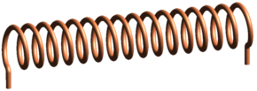
An inductor, also called a coil, choke, or reactor, is a passive two-terminal electrical component that stores energy in a magnetic field when electric current flows through it. An inductor typically consists of an insulated wire wound into a coil.

<span class="mw-page-title-main">Lorentz force</span> Force acting on charged particles in electric and magnetic fields

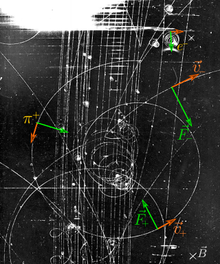
In physics, specifically in electromagnetism, the Lorentz force is the combination of electric and magnetic force on a point charge due to electromagnetic fields. A particle of charge q moving with a velocity v in an electric field E and a magnetic field B experiences a force of

<span class="mw-page-title-main">Maxwell's equations</span> Equations describing classical electromagnetism

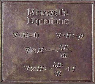
Maxwell's equations, or Maxwell–Heaviside equations, are a set of coupled partial differential equations that, together with the Lorentz force law, form the foundation of classical electromagnetism, classical optics, electric and magnetic circuits. The equations provide a mathematical model for electric, optical, and radio technologies, such as power generation, electric motors, wireless communication, lenses, radar, etc. They describe how electric and magnetic fields are generated by charges, currents, and changes of the fields. The equations are named after the physicist and mathematician James Clerk Maxwell, who, in 1861 and 1862, published an early form of the equations that included the Lorentz force law. Maxwell first used the equations to propose that light is an electromagnetic phenomenon. The modern form of the equations in their most common formulation is credited to Oliver Heaviside.

<span class="mw-page-title-main">Magnetic field</span> Distribution of magnetic force

A magnetic field is a physical field that describes the magnetic influence on moving electric charges, electric currents, and magnetic materials. A moving charge in a magnetic field experiences a force perpendicular to its own velocity and to the magnetic field. A permanent magnet's magnetic field pulls on ferromagnetic materials such as iron, and attracts or repels other magnets. In addition, a nonuniform magnetic field exerts minuscule forces on "nonmagnetic" materials by three other magnetic effects: paramagnetism, diamagnetism, and antiferromagnetism, although these forces are usually so small they can only be detected by laboratory equipment. Magnetic fields surround magnetized materials, electric currents, and electric fields varying in time. Since both strength and direction of a magnetic field may vary with location, it is described mathematically by a function assigning a vector to each point of space, called a vector field.

<span class="mw-page-title-main">Inductive coupling</span> Electrical circuit coupling using induction

In electrical engineering, two conductors are said to be inductively coupled or magnetically coupled when they are configured in a way such that change in current through one wire induces a voltage across the ends of the other wire through electromagnetic induction. A changing current through the first wire creates a changing magnetic field around it by Ampere's circuital law. The changing magnetic field induces an electromotive force (EMF) voltage in the second wire by Faraday's law of induction. The amount of inductive coupling between two conductors is measured by their mutual inductance.

Flux describes any effect that appears to pass or travel through a surface or substance. Flux is a concept in applied mathematics and vector calculus which has many applications to physics. For transport phenomena, flux is a vector quantity, describing the magnitude and direction of the flow of a substance or property. In vector calculus flux is a scalar quantity, defined as the surface integral of the perpendicular component of a vector field over a surface.

<span class="mw-page-title-main">Magnetic flux</span> Surface integral of the magnetic field

In physics, specifically electromagnetism, the magnetic flux through a surface is the surface integral of the normal component of the magnetic field B over that surface. It is usually denoted Φ or ΦB. The SI unit of magnetic flux is the weber, and the CGS unit is the maxwell. Magnetic flux is usually measured with a fluxmeter, which contains measuring coils, and it calculates the magnetic flux from the change of voltage on the coils.

<span class="mw-page-title-main">Electromotive force</span> Electrical action produced by a non-electrical source

In electromagnetism and electronics, electromotive force is an energy transfer to an electric circuit per unit of electric charge, measured in volts. Devices called electrical transducers provide an emf by converting other forms of energy into electrical energy. Other electrical equipment also produce an emf, such as batteries, which convert chemical energy, and generators, which convert mechanical energy. This energy conversion is achieved by physical forces applying physical work on electric charges. However, electromotive force itself is not a physical force, and ISO/IEC standards have deprecated the term in favor of source voltage or source tension instead.

<span class="mw-page-title-main">Inductance</span> Property of electrical conductors

Inductance is the tendency of an electrical conductor to oppose a change in the electric current flowing through it. The electric current produces a magnetic field around the conductor. The magnetic field strength depends on the magnitude of the electric current, and follows any changes in the magnitude of the current. From Faraday's law of induction, any change in magnetic field through a circuit induces an electromotive force (EMF) (voltage) in the conductors, a process known as electromagnetic induction. This induced voltage created by the changing current has the effect of opposing the change in current. This is stated by Lenz's law, and the voltage is called back EMF.

<span class="mw-page-title-main">Lenz's law</span> Electromagnetic opposition to change

Lenz's law states that the direction of the electric current induced in a conductor by a changing magnetic field is such that the magnetic field created by the induced current opposes changes in the initial magnetic field. It is named after physicist Heinrich Lenz, who formulated it in 1834.

<span class="mw-page-title-main">Skin effect</span> Tendency of AC current flow in a conductors outer layer

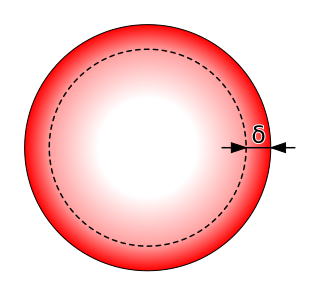
In electromagnetism, skin effect is the tendency of an alternating electric current (AC) to become distributed within a conductor such that the current density is largest near the surface of the conductor and decreases exponentially with greater depths in the conductor. It is caused by opposing eddy currents induced by the changing magnetic field resulting from the alternating current. The electric current flows mainly at the skin of the conductor, between the outer surface and a level called the skin depth. Skin depth depends on the frequency of the alternating current; as frequency increases, current flow becomes more concentrated near the surface, resulting in less skin depth. Skin effect reduces the effective cross-section of the conductor and thus increases its effective resistance. At 60 Hz in copper, skin depth is about 8.5 mm. At high frequencies, skin depth becomes much smaller.

<span class="mw-page-title-main">Eddy current</span> Loops of electric current induced within conductors by a changing magnetic field

In electromagnetism, an eddy current is a loop of electric current induced within conductors by a changing magnetic field in the conductor according to Faraday's law of induction or by the relative motion of a conductor in a magnetic field. Eddy currents flow in closed loops within conductors, in planes perpendicular to the magnetic field. They can be induced within nearby stationary conductors by a time-varying magnetic field created by an AC electromagnet or transformer, for example, or by relative motion between a magnet and a nearby conductor. The magnitude of the current in a given loop is proportional to the strength of the magnetic field, the area of the loop, and the rate of change of flux, and inversely proportional to the resistivity of the material. When graphed, these circular currents within a piece of metal look vaguely like eddies or whirlpools in a liquid.

"A Dynamical Theory of the Electromagnetic Field" is a paper by James Clerk Maxwell on electromagnetism, published in 1865. In the paper, Maxwell derives an electromagnetic wave equation with a velocity for light in close agreement with measurements made by experiment, and deduces that light is an electromagnetic wave.

<span class="mw-page-title-main">Faraday's law of induction</span> Basic law of electromagnetism

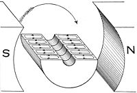
Faraday's law of induction is a law of electromagnetism predicting how a magnetic field will interact with an electric circuit to produce an electromotive force (emf). This phenomenon, known as electromagnetic induction, is the fundamental operating principle of transformers, inductors, and many types of electric motors, generators and solenoids.

<span class="mw-page-title-main">Magnetic circuit</span> Closed loop path containing a magnetic flux

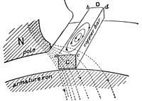
A magnetic circuit is made up of one or more closed loop paths containing a magnetic flux. The flux is usually generated by permanent magnets or electromagnets and confined to the path by magnetic cores consisting of ferromagnetic materials like iron, although there may be air gaps or other materials in the path. Magnetic circuits are employed to efficiently channel magnetic fields in many devices such as electric motors, generators, transformers, relays, lifting electromagnets, SQUIDs, galvanometers, and magnetic recording heads.

<span class="mw-page-title-main">Faraday paradox</span> Apparent paradox with Faradays law of induction

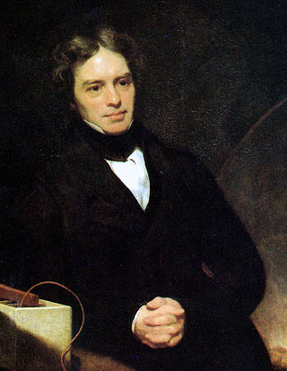
The Faraday paradox or Faraday's paradox is any experiment in which Michael Faraday's law of electromagnetic induction appears to predict an incorrect result. The paradoxes fall into two classes:

<span class="mw-page-title-main">History of Maxwell's equations</span>

In the beginning of the 19th century, many experimental and theoretical works had been accomplished in the understanding of electromagnetics. In the 1780s, Charles-Augustin de Coulomb established his law of electrostatics. In 1825, André-Marie Ampère published his Ampère's force law. Michael Faraday discovered the electromagnetic induction through his experiments and conceptually, he emphasized the lines of forces in this electromagnetic induction. In 1834, Emil Lenz solved the problem of the direction of the induction, and Franz Ernst Neumann wrote down the equation to calculate the induced force by change of magnetic flux. However, these experimental results and rules were not well organized and sometimes confusing to scientists. A comprehensive summary of the electrodynamic principles was in urgent need at that time.

The Maxwell-Lodge effect is a phenomenon of electromagnetic induction in which an electric charge, near a solenoid in which current changes slowly, feels an electromotive force (e.m.f.) even if the magnetic field is practically static inside and null outside. It can be considered a classical analogue of the quantum mechanical Aharonov–Bohm effect, where instead the field is exactly static inside and null outside.

Blondel's experiments are a series of experiments performed by physicist André Blondel in 1914 in order to determine what was the most general law of electromagnetic induction. In fact, noted Blondel, "Significant discussions have been raised repeatedly on the question of what is the most general law of induction: we should consider the electromotive force (e.m.f.) as the product of any variation of magnetic fluxsurrounding a conductor or of the fact that the conductor sweeps part of this flux?".

References

Notes

  1. The EMF is the voltage that would be measured by cutting the wire to create an open circuit, and attaching a voltmeter to the leads. Mathematically, is defined as the energy available from a unit charge that has traveled once around the wire loop. [13] [14] [15]

References

  1. Poyser, A. W. (1892). Magnetism and Electricity: A Manual for Students in Advanced Classes. London and New York: Longmans, Green, & Co. p.  285.
  2. 1 2 Giancoli, Douglas C. (1998). Physics: Principles with Applications (5th ed.). pp.  623–624.
  3. Ulaby, Fawwaz (2007). Fundamentals of applied electromagnetics (5th ed.). Pearson: Prentice Hall. p. 255. ISBN   978-0-13-241326-8.
  4. "Joseph Henry". Distinguished Members Gallery, National Academy of Sciences. Archived from the original on 2013-12-13. Retrieved 2006-11-30.
  5. Errede, Steven (2007). "A Brief History of The Development of Classical Electrodynamics" (PDF).
  6. "Electromagnetism". Smithsonian Institution Archives.
  7. Michael Faraday, by L. Pearce Williams, pp. 182–183
  8. Michael Faraday, by L. Pearce Williams, pp. 191–195
  9. 1 2 Michael Faraday, by L. Pearce Williams, p. 510
  10. Maxwell, James Clerk (1904), A Treatise on Electricity and Magnetism, Vol. II, Third Edition. Oxford University Press, pp. 178–179 and 189.
  11. "Archives Biographies: Michael Faraday", The Institution of Engineering and Technology.
  12. Good, R. H. (1999). Classical Electromagnetism. Saunders College Publishing. p. 107. ISBN   0-03-022353-9.
  13. Feynman, R. P.; Leighton, R. B.; Sands, M. L. (2006). The Feynman Lectures on Physics, Volume 2. Pearson/Addison-Wesley. p. 17-2. ISBN   0-8053-9049-9.
  14. Griffiths, D. J. (1999). Introduction to Electrodynamics (3rd ed.). Prentice Hall. pp.  301–303. ISBN   0-13-805326-X.
  15. Tipler, P. A.; Mosca, G. (2003). Physics for Scientists and Engineers (5th ed.). W.H. Freeman. p. 795. ISBN   978-0716708100.
  16. Jordan, E.; Balmain, K. G. (1968). Electromagnetic Waves and Radiating Systems (2nd ed.). Prentice-Hall. p.  100. ISBN   978-0132499958.
  17. Hayt, W. (1989). Engineering Electromagnetics (5th ed.). McGraw-Hill. p.  312. ISBN   0-07-027406-1.
  18. Schmitt, R. (2002). Electromagnetics Explained . Newnes. p.  75. ISBN   978-0750674034.
  19. Whelan, P. M.; Hodgeson, M. J. (1978). Essential Principles of Physics (2nd ed.). John Murray. ISBN   0-7195-3382-1.
  20. Nave, C. R. "Faraday's Law". HyperPhysics . Georgia State University . Retrieved 2011-08-29.
  21. Maxwell, J. C. (1861). "On physical lines of force". Philosophical Magazine . 90 (139): 11–23. doi: 10.1080/14786446108643033 .
  22. Griffiths, D. J. (1999). Introduction to Electrodynamics (3rd ed.). Prentice Hall. pp.  301–303. ISBN   0-13-805326-X. Note that the law relating flux to EMF, which this article calls "Faraday's law", is referred to by Griffiths as the "universal flux rule". He uses the term "Faraday's law" to refer to what this article calls the "Maxwell–Faraday equation".
  23. "The flux rule" is the terminology that Feynman uses to refer to the law relating magnetic flux to EMF. Feynman, R. P.; Leighton, R. B.; Sands, M. L. (2006). The Feynman Lectures on Physics, Volume II. Pearson/Addison-Wesley. p. 17-2. ISBN   0-8053-9049-9.[ permanent dead link ]
  24. Einstein, A. (1905). "Zur Elektrodynamik bewegter Körper" (PDF). Annalen der Physik . 17 (10): 891–921. Bibcode:1905AnP...322..891E. doi: 10.1002/andp.19053221004 .
    Translated in Einstein, A. (1923). "On the Electrodynamics of Moving Bodies" (PDF). The Principle of Relativity. Jeffery, G.B.; Perret, W. (transl.). London: Methuen and Company.
  25. 1 2 3 Images and reference text are from the public domain book: Hawkins Electrical Guide , Volume 1, Chapter 19: Theory of the Armature, pp. 270–273, Copyright 1917 by Theo. Audel & Co., Printed in the United States

Further reading