Rotor (electric)

Last updated

A selection of various types of rotors Various motor rotor TICI.jpg
A selection of various types of rotors
Rotor from Hoover Dam generator Hoover dam rotor.jpg
Rotor from Hoover Dam generator

The rotor is a moving component of an electromagnetic system in the electric motor, electric generator, or alternator. Its rotation is due to the interaction between the windings and magnetic fields which produces a torque around the rotor's axis. [1]

Contents

Early development

An early example of electromagnetic rotation was the first rotary machine built by Ányos Jedlik with electromagnets and a commutator, in 1826-27. [2] Other pioneers in the field of electricity include Hippolyte Pixii who built an alternating current generator in 1832, and William Ritchie's construction of an electromagnetic generator with four rotor coils, a commutator and brushes, also in 1832. Development quickly included more useful applications such as Moritz Hermann Jacobi's motor that could lift 10 to 12 pounds with a speed of one foot per second, about 15 watts of mechanical power in 1834. In 1835, Francis Watkins describes an electrical "toy" he created; he is generally regarded as one of the first to understand the interchangeability of motor and generator.

Type and construction of rotors

Induction (asynchronous) motors, generators and alternators (synchronous) have an electromagnetic system consisting of a stator and rotor. There are two designs for the rotor in an induction motor: squirrel cage and wound. In generators and alternators, the rotor designs are salient pole or cylindrical.

Squirrel-cage rotor

The squirrel-cage rotor consists of laminated steel in the core with evenly spaced bars of copper or aluminum placed axially around the periphery, permanently shorted at the ends by the end rings. [3] This simple and rugged construction makes it the favorite for most applications. The assembly has a twist: the bars are slanted, or skewed, to reduce magnetic hum and slot harmonics and to reduce the tendency of locking. Housed in the stator, the rotor and stator teeth can lock when they are in equal number and the magnets position themselves equally apart, opposing rotation in both directions. [3] Bearings at each end mount the rotor in its housing, with one end of the shaft protruding to allow the attachment of the load. In some motors, there is an extension at the non-driving end for speed sensors or other electronic controls. The generated torque forces motion through the rotor to the load.

Wound rotor

The wound rotor is a cylindrical core made of steel lamination with slots to hold the wires for its 3-phase windings which are evenly spaced at 120 electrical degrees apart and connected in a 'Y' configuration. [4] The rotor winding terminals are brought out and attached to the three slips rings with brushes, on the shaft of the rotor. [5] Brushes on the slip rings allow for external three-phase resistors to be connected in series to the rotor windings for providing speed control. [6] The external resistances become a part of the rotor circuit to produce a large torque when starting the motor. As the motor speeds up, the resistances can be reduced to zero. [5]

Salient pole rotor

A salient pole rotor is built upon a stack of "star shaped" steel laminations, typically with 2 or 3 or 4 or 6, maybe even 18 or more "radial prongs" sticking out from the middle, each of which is wound with copper wire to form a discrete outward facing electromagnet pole. The inward facing ends of each prong are magnetically grounded into the common central body of the rotor. The poles are supplied by direct current or magnetized by permanent magnets. [7] The armature with a three-phase winding is on the stator where voltage is induced. Direct current (DC), from an external exciter or from a diode bridge mounted on the rotor shaft, produces a magnetic field and energizes the rotating field windings and alternating current energizes the armature windings simultaneously. [8] [7]

A salient pole ends in a pole shoe, a high-permeability part with an outer surface shaped as a segment of a cylinder to homogenize the distribution of the magnetic flux to the stator. [9]

Non-salient rotor

The cylindrical shaped rotor is made of a solid steel shaft with slots running along the outside length of the cylinder for holding the field windings of the rotor which are laminated copper bars inserted into the slots and is secured by wedges. [10] The slots are insulated from the windings and are held at the end of the rotor by slip rings. An external direct current (DC) source is connected to the concentrically mounted slip rings with brushes running along the rings. [8] The brushes make electrical contact with the rotating slip rings. DC current is also supplied through brushless excitation from a rectifier mounted on the machine shaft that converts alternating current to direct current.

Operating principle

In a three-phase induction machine, alternating current supplied to the stator windings energizes it to create a rotating magnetic flux. [11] The flux generates a magnetic field in the air gap between the stator and the rotor and induces a voltage which produces current through the rotor bars. The rotor circuit is shorted and current flows in the rotor conductors. [5] The action of the rotating flux and the current produces a force that generates a torque to start the motor. [11]

An alternator rotor is made up of a wire coil enveloped around an iron core. [12] The magnetic component of the rotor is made from steel laminations to aid stamping conductor slots to specific shapes and sizes. As currents travel through the wire coil a magnetic field is created around the core, which is referred to as field current. [1] The field current strength controls the power level of the magnetic field. Direct current (DC) drives the field current in one direction, and is delivered to the wire coil by a set of brushes and slip rings. Like any magnet, the magnetic field produced has a north and a south pole. The normal clockwise direction of the motor that the rotor is powering can be manipulated by using the magnets and magnetic fields installed in the design of the rotor, allowing the motor to run in reverse or counterclockwise. [1] [12]

Characteristics of rotors

This rotor rotates at a speed less than the stator rotating magnetic field or synchronous speed.
Rotor slip provides necessary induction of rotor currents for motor torque, which is in proportion to slip.
When rotor speed increases, the slip decreases.
Increasing the slip increases induced motor current, which in turn increases rotor current, resulting in a higher torque for increase load demands.
This rotor operates at constant speed and has lower starting current
External resistance added to rotor circuit, increases starting torque
Motor running efficiency improves as external resistance is reduced when motor speed up.
Higher torque and speed control
This rotor operates at a speed below 1500 rpm (revolutions per minute) and 40% of its rated torque without excitation
It has a large diameter and short axial length
Air gap is non uniform
Rotor has low mechanical strength
The rotor operates at speed between 1500-3600 rpm
It has strong mechanical strength
Air gap is uniform
Its diameter is small and has a large axial length and requires a higher torque than salient pole rotor

Rotor equations

Rotor bar voltage

The rotating magnetic field induces a voltage in the rotor bars as it passes over them. This equation applies to induced voltage in the rotor bars. [11]

where:

= induced voltage
= magnetic field
= conductor length
= synchronous speed
= conductor speed

Torque in rotor

A torque is produced by the force produced through the interactions of the magnetic field and current as expressed by the given: Ibid

where:

= force
= torque
= radius of rotor rings
= rotor bar

Induction motor slip

A stator magnetic field rotates at synchronous speed, Ibid

where:

= frequency
= number of poles

If = rotor speed, the slip, S for an induction motor is expressed as:

mechanical speed of rotor, in terms of slip and synchronous speed:

Relative speed of slip:

Frequency of induced voltages and currents

See also

Related Research Articles

<span class="mw-page-title-main">Electric motor</span> Machine that converts electrical energy into mechanical energy

An electric motor is an electrical machine that converts electrical energy into mechanical energy. Most electric motors operate through the interaction between the motor's magnetic field and electric current in a wire winding to generate force in the form of torque applied on the motor's shaft. An electric generator is mechanically identical to an electric motor, but operates in reverse, converting mechanical energy into electrical energy.

<span class="mw-page-title-main">Electric generator</span> Device that converts other energy to electrical energy

In electricity generation, a generator is a device that converts motion-based power or fuel-based power into electric power for use in an external circuit. Sources of mechanical energy include steam turbines, gas turbines, water turbines, internal combustion engines, wind turbines and even hand cranks. The first electromagnetic generator, the Faraday disk, was invented in 1831 by British scientist Michael Faraday. Generators provide nearly all the power for electrical grids.

<span class="mw-page-title-main">Alternator</span> Device converting mechanical into electrical energy

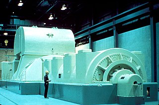
An alternator is an electrical generator that converts mechanical energy to electrical energy in the form of alternating current. For reasons of cost and simplicity, most alternators use a rotating magnetic field with a stationary armature. Occasionally, a linear alternator or a rotating armature with a stationary magnetic field is used. In principle, any AC electrical generator can be called an alternator, but usually the term refers to small rotating machines driven by automotive and other internal combustion engines.

<span class="mw-page-title-main">Induction motor</span> Type of AC electric motor

An induction motor or asynchronous motor is an AC electric motor in which the electric current in the rotor that produces torque is obtained by electromagnetic induction from the magnetic field of the stator winding. An induction motor therefore needs no electrical connections to the rotor. An induction motor's rotor can be either wound type or squirrel-cage type.

<span class="mw-page-title-main">Synchronous motor</span> Type of AC motor

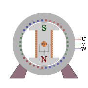
A synchronous electric motor is an AC electric motor in which, at steady state, the rotation of the shaft is synchronized with the frequency of the supply current; the rotation period is exactly equal to an integral number of AC cycles. Synchronous motors use electromagnets as the stator of the motor which create a magnetic field that rotates in time with the oscillations of the current. The rotor with permanent magnets or electromagnets turns in step with the stator field at the same rate and as a result, provides the second synchronized rotating magnet field. A synchronous motor is termed doubly fed if it is supplied with independently excited multiphase AC electromagnets on both the rotor and stator.

<span class="mw-page-title-main">DC motor</span> Motor which works on direct current

A DC motor is an electrical motor that uses direct current (DC) to produce mechanical force. The most common types rely on magnetic forces produced by currents in the coils. Nearly all types of DC motors have some internal mechanism, either electromechanical or electronic, to periodically change the direction of current in part of the motor.

<span class="mw-page-title-main">Squirrel-cage rotor</span> Rotating part of the common squirrel-cage induction motor

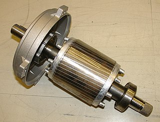
A squirrel-cage rotor is the rotating part of the common squirrel-cage induction motor. It consists of a cylinder of steel laminations, with aluminum or copper conductors embedded in its surface. In operation, the non-rotating stator winding is connected to an alternating current power source; the alternating current in the stator produces a rotating magnetic field. The rotor winding has current induced in it by the stator field, like a transformer except that the current in the rotor is varying at the stator field rotation rate minus the physical rotation rate. The interaction of the magnetic fields of currents in the stator and rotor produce a torque on the rotor.

<span class="mw-page-title-main">Shaded-pole motor</span> Type of AC single-phase induction motor

The shaded-pole motor is the original type of AC single-phase motor, dating back to at least as early as 1890. A shaded-pole motor is a small motor with either two or four poles, in which the auxiliary winding is composed of a copper ring or bar surrounding a portion of each pole to produce a weakly rotating magnetic field. When single phase AC supply is applied to the stator winding, due to shading provided to the poles, a rotating magnetic field is generated. This auxiliary single-turn winding is called a shading coil. Currents induced in this coil by the magnetic field create a second electrical phase by delaying the phase of magnetic flux change for that pole enough to provide a 2-phase rotating magnetic field. The direction of rotation is from the unshaded side to the shaded (ring) side of the pole. Since the phase angle between the shaded and unshaded sections is small, shaded-pole motors produce only a small starting torque relative to torque at full speed. Shaded-pole motors of the asymmetrical type shown are only reversible by disassembly and flipping over the stator, though some similar looking motors have small, switch-shortable auxiliary windings of thin wire instead of thick copper bars and can reverse electrically. Another method of electrical reversing involves four coils.

<span class="mw-page-title-main">Rotary converter</span> Electrical machine

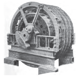
A rotary converter is a type of electrical machine which acts as a mechanical rectifier, inverter or frequency converter.

<span class="mw-page-title-main">Universal motor</span> Type of electric motor

The universal motor is a type of electric motor that can operate on either AC or DC power and uses an electromagnet as its stator to create its magnetic field. It is a commutated series-wound motor where the stator's field coils are connected in series with the rotor windings through a commutator. It is often referred to as an AC series motor. The universal motor is very similar to a DC series motor in construction, but is modified slightly to allow the motor to operate properly on AC power. This type of electric motor can operate well on AC because the current in both the field coils and the armature will alternate synchronously with the supply. Hence the resulting mechanical force will occur in a consistent direction of rotation, independent of the direction of applied voltage, but determined by the commutator and polarity of the field coils.

<span class="mw-page-title-main">Field coil</span> Electromagnet used to generate a magnetic field in an electro-magnetic machine

A field coil is an electromagnet used to generate a magnetic field in an electro-magnetic machine, typically a rotating electrical machine such as a motor or generator. It consists of a coil of wire through which a current flows.

<span class="mw-page-title-main">Repulsion motor</span> Type of AC electric motor

A repulsion motor is a type of electric motor which runs on alternating current (AC). It was formerly used as a traction motor for electric trains but has been superseded by other types of motors. Repulsion motors are classified as single phase motors.

<span class="mw-page-title-main">Reluctance motor</span> Type of electric motor

A reluctance motor is a type of electric motor that induces non-permanent magnetic poles on the ferromagnetic rotor. The rotor does not have any windings. It generates torque through magnetic reluctance.

<span class="mw-page-title-main">AC motor</span> Electric motor driven by an AC electrical input

An AC motor is an electric motor driven by an alternating current (AC). The AC motor commonly consists of two basic parts, an outside stator having coils supplied with alternating current to produce a rotating magnetic field, and an inside rotor attached to the output shaft producing a second rotating magnetic field. The rotor magnetic field may be produced by permanent magnets, reluctance saliency, or DC or AC electrical windings.

An induction generator or asynchronous generator is a type of alternating current (AC) electrical generator that uses the principles of induction motors to produce electric power. Induction generators operate by mechanically turning their rotors faster than synchronous speed. A regular AC induction motor usually can be used as a generator, without any internal modifications. Because they can recover energy with relatively simple controls, induction generators are useful in applications such as mini hydro power plants, wind turbines, or in reducing high-pressure gas streams to lower pressure.

<span class="mw-page-title-main">Dynamo</span> Electrical generator that produces direct current with the use of a commutator

A dynamo is an electrical generator that creates direct current using a commutator. Dynamos were the first electrical generators capable of delivering power for industry, and the foundation upon which many other later electric-power conversion devices were based, including the electric motor, the alternating-current alternator, and the rotary converter.

In electrical engineering, electric machine is a general term for machines using electromagnetic forces, such as electric motors, electric generators, and others. They are electromechanical energy converters: an electric motor converts electricity to mechanical power while an electric generator converts mechanical power to electricity. The moving parts in a machine can be rotating or linear. Besides motors and generators, a third category often included is transformers, which although they do not have any moving parts are also energy converters, changing the voltage level of an alternating current.

<span class="mw-page-title-main">Switched reluctance motor</span> Externally controlled electric motor that runs by reluctance torque

The switched reluctance motor (SRM) is an electric motor that runs by reluctance torque and thus is a subgroup in reluctance motors. Unlike common brushed DC motor types, power is delivered to windings in the stator (case) rather than the rotor. This greatly simplifies mechanical design as power does not have to be delivered to a moving part which eliminates the need for a commutator, but it complicates the electrical design as some sort of switching system needs to be used to deliver power to the different windings. Electronic devices can precisely time the switching of currents, facilitating SRM configurations. Its main drawback is torque ripple. Controller technology that limits torque ripple at low speeds has been demonstrated. Sources disagree on whether it is a type of stepper motor.

A permanent magnet synchronous generator is a generator where the excitation field is provided by a permanent magnet instead of a coil. The term synchronous refers here to the fact that the rotor and magnetic field rotate with the same speed, because the magnetic field is generated through a shaft mounted permanent magnet mechanism and current is induced into the stationary armature.

Electromagnetically induced acoustic noise (and vibration), electromagnetically excited acoustic noise, or more commonly known as coil whine, is audible sound directly produced by materials vibrating under the excitation of electromagnetic forces. Some examples of this noise include the mains hum, hum of transformers, the whine of some rotating electric machines, or the buzz of fluorescent lamps. The hissing of high voltage transmission lines is due to corona discharge, not magnetism.

References

  1. 1 2 3 Staff. "Understanding Alternators. What Is an Alternator and How Does It Work." N.p., n.d. Web. 24 November 2014 "Understanding Alternators. What is an Alternator and How Does It Work". Archived from the original on 11 December 2014. Retrieved 11 December 2014..
  2. Ing Doppelbauer Martin Dr. The Invention of the Electric Motor 1800-1854. 29th Web. November, 2014.: Web. 28th November, 2014.http://www.eti.kit.edu/english/1376.php
  3. 1 2 Parekh, Rakesh. 2003. AC Induction Fundamentals 30 November 2014 Web. 29 November 2014.http://ww1.microchip.com/downloads/en/AppNotes/00887a.pdf
  4. Industrical-Electronics. Three-Phase Wound-Rotor Induction Motor. 10 November 2014. Web. 1 December 2014 "Three-Phase Wound-Rotor Induction Motor". Archived from the original on 17 February 2015. Retrieved 10 December 2014.
  5. 1 2 3 University of Taxila. Three Induction Motor. 2012. Web. 28 November 2014 http://web.uettaxila.edu.pk/CMS/SP2012/etEMbs/notes%5CThree%20Phase%20Induction%20Motors.pdf Archived 23 January 2013 at the Wayback Machine
  6. Fathizadeh Masoud, PhD, PE. Induction Motors. n.d. Web. 24 November 2014. "Archived copy" (PDF). Archived (PDF) from the original on 10 October 2015. Retrieved 25 November 2014.{{cite web}}: CS1 maint: archived copy as title (link)
  7. 1 2 Cardell, J. Principles of Operation Of Synchronous Machine (n.d.). Web.http://www.science.smith.edu/~jcardell/Courses/EGR325/Readings/SynchGenWiley.pdf
  8. 1 2 Donohoe. SYNCHRONOUS MACHINES.n.d. Web. 30 November 2014. http://www.ece.msstate.edu/~donohoe/ece3614synchronous_machines.pdf
  9. U.S. Patent 9,742,224
  10. O&M Consulting Services. Basic AC Electrical Generators. n.d. Web. 2 December 2014. "American Society of Power Engineers, Inc" (PDF). Archived (PDF) from the original on 3 March 2016. Retrieved 2 January 2016.
  11. 1 2 3 Shahl, Suad Ibrahim.Three-phase Induction Machine. n.d. Web. 2 December 2014 "Archived copy" (PDF). Archived (PDF) from the original on 5 November 2015. Retrieved 12 December 2014.{{cite web}}: CS1 maint: archived copy as title (link)
  12. 1 2 Slemon, Gordon. Encyclopædia Britannica Inc., 17 March 2014. Web. 25 Nov. 2014 "Electric motor -- Britannica Online Encyclopedia". Archived from the original on 23 October 2014. Retrieved 25 November 2014.