Vector control, also called field-oriented control (FOC), is a variable-frequency drive (VFD) control method in which the stator currents of a three-phaseAC or brushless DC electric motor are identified as two orthogonal components that can be visualized with a vector. One component defines the magnetic flux of the motor, the other the torque. The control system of the drive calculates the corresponding current component references from the flux and torque references given by the drive's speed control. Typically proportional-integral (PI) controllers are used to keep the measured current components at their reference values. The pulse-width modulation of the variable-frequency drive defines the transistor switching according to the stator voltage references that are the output of the PI current controllers.[1]
FOC is used to control ACsynchronous and induction motors.[2] It was originally developed for high-performance motor applications that are required to operate smoothly over the full speed range, generate full torque at zero speed, and have high dynamic performance including fast acceleration and deceleration. However, it is becoming increasingly attractive for lower performance applications as well due to FOC's motor size, cost and power consumption reduction superiority.[3][4] It is expected that with increasing computational power of the microprocessors it will eventually nearly universally displace single-variable scalar control (volts-per-Hertz, V/f control).[5][6]
Block diagram from Blaschke's 1971 US patent application
Technische Universität Darmstadt's K. Hasse and Siemens' F. Blaschke pioneered vector control of AC motors starting in 1968 and in the early 1970s. Hasse in terms of proposing indirect vector control, Blaschke in terms of proposing direct vector control.[7][8] Technical University Braunschweig's Werner Leonhard further developed FOC techniques and was instrumental in opening up opportunities for AC drives to be a competitive alternative to DC drives.[9][10]
Yet it was not until after the commercialization of microprocessors, that is in the early 1980s, that general purpose AC drives became available.[11][12] Barriers to use FOC for AC drive applications included higher cost and complexity and lower maintainability compared to DC drives, FOC having until then required many electronic components in terms of sensors, amplifiers and so on.[13]
The Park transformation has long been widely used in the analysis and study of synchronous and induction machines. The transformation is by far the single most important concept needed for an understanding of how FOC works, the concept having been first conceptualized in a 1929 paper authored by Robert H. Park.[14] Park's paper was ranked second most important in terms of impact from among all power engineering related papers ever published in the twentieth century. The novelty of Park's work involves his ability to transform any related machine's linear differential equation set from one with time varying coefficients to another with time invariant coefficients [15] resulting in a linear time-invariant system or LTI system.
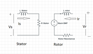
While the analysis of AC drive controls can be technically quite involved ("See also" section), such analysis invariably starts with modeling of the drive-motor circuit involved along the lines of accompanying signal flow graph and equations.[16]
Induction motor model equations
where
Basic parameter symbols
i
current
k
coupling factor of respective winding
l
inductance
r
resistance
t
time
T
torque
u
voltage
flux linkage
normalized time
time constant (T.C.) with subscript
angular velocity
total leakage inductance
Subscripts and superscripts
e
electromechanical
i
induced voltage
k
referred to k-coordinates
L
load
m
mutual (inductance)
m
mechanical (T.C., angular velocity)
r
rotor
R
rated value
s
stator
denotes transient time constant
Signal Flow Graph (SFG) for Induction Motor(d,q) Coordinate System Superimposed on Three-Phase Induction MotorSimplified Indirect FOC Block Diagram Simplified Direct FOC Block Diagram Sensorless FOC Block Diagram
In vector control, an AC induction or synchronous motor is controlled under all operating conditions like a separately excited DC motor.[21] That is, the AC motor behaves like a DC motor in which the field flux linkage and armature flux linkage created by the respective field and armature (or torque component) currents are orthogonally aligned such that, when torque is controlled, the field flux linkage is not affected, hence enabling dynamic torque response.
Vector control accordingly generates a three-phase PWM motor voltage output derived from a complex voltage vector to control a complex current vector derived from motor's three-phase stator current input through projections or rotations back and forth between the three-phase speed and time dependent system and these vectors' rotating reference-frame two-coordinate time invariant system.[22]
Such complex stator current space vector can be defined in a (d,q) coordinate system with orthogonal components along d (direct) and q (quadrature) axes such that field flux linkage component of current is aligned along the d axis and torque component of current is aligned along the q axis.[21] The induction motor's (d,q) coordinate system can be superimposed to the motor's instantaneous (a,b,c) three-phase sinusoidal system as shown in accompanying image (phases b & c not shown for clarity). Components of the (d,q) system current vector allow conventional control such as proportional and integral, or PI, control, as with a DC motor.
Projections associated with the (d,q) coordinate system typically involve:[16][22][23]
Forward projection from instantaneous currents to (a,b,c) complex stator current space vector representation of the three-phase sinusoidal system.
Forward three-to-two phase, (a,b,c)-to-(,) projection using the Clarke transformation. Vector control implementations usually assume ungrounded motor with balanced three-phase currents such that only two motor current phases need to be sensed. Also, backward two-to-three phase, (,)-to-(a,b,c) projection uses space vector PWM modulator or inverse Clarke transformation and one of the other PWM modulators.
Forward and backward two-to-two phase,(,)-to-(d,q) and (d,q)-to-(,) projections using the Park and inverse Park transformations, respectively.
The idea of using the park transform is to convert the system of three phase currents and voltages into a two coordinate linear time-invariant system. By making the system LTI is what enables the use of simple and easy to implement PI controllers, and also simplifies the control of flux and torque producing currents.
However, it is not uncommon for sources to use combined transform three-to-two, (a,b,c)-to-(d,q) and inverse projections.
While (d,q) coordinate system rotation can arbitrarily be set to any speed, there are three preferred speeds or reference frames:[17]
Stationary reference frame where (d,q) coordinate system does not rotate;
Synchronously rotating reference frame where (d,q) coordinate system rotates at synchronous speed;
Rotor reference frame where (d,q) coordinate system rotates at rotor speed.
Decoupled torque and field currents can thus be derived from raw stator current inputs for control algorithm development.[24]
Whereas magnetic field and torque components in DC motors can be operated relatively simply by separately controlling the respective field and armature currents, economical control of AC motors in variable speed application has required development of microprocessor-based controls[24] with all AC drives now using powerful DSP (digital signal processing) technology.[25]
Inverters can be implemented as either open-loop sensorless or closed-loop FOC, the key limitation of open-loop operation being minimum speed possible at 100% torque, namely, about 0.8Hz compared to standstill for closed-loop operation.[9]
There are two vector control methods, direct or feedback vector control (DFOC) and indirect or feedforward vector control (IFOC), IFOC being more commonly used because in closed-loop mode such drives more easily operate throughout the speed range from zero speed to high-speed field-weakening.[26] In DFOC, flux magnitude and angle feedback signals are directly calculated using so-called voltage or current models. In IFOC, flux space angle feedforward and flux magnitude signals first measure stator currents and rotor speed for then deriving flux space angle proper by summing the rotor angle corresponding to the rotor speed and the calculated reference value of slip angle corresponding to the slip frequency.[27][28]
Sensorless control (see Sensorless FOC Block Diagram) of AC drives is attractive for cost and reliability considerations. Sensorless control requires derivation of rotor speed information from measured stator voltage and currents in combination with open-loop estimators or closed-loop observers.[16][20]
Application
Stator phase currents are measured, converted to complex space vector in (a,b,c) coordinate system.
Rotor flux linkage vector is estimated by multiplying the stator current vector with magnetizing inductance Lm and low-pass filtering the result with the rotor no-load time constant Lr/Rr, namely, the rotor inductance to rotor resistance ratio.
Current vector is converted to (d,q) coordinate system.
d-axis component of the stator current vector is used to control the rotor flux linkage and the imaginary q-axis component is used to control the motor torque. While PI controllers can be used to control these currents, bang-bang type current control provides better dynamic performance. [citation needed]
PI controllers provide (d,q) coordinate voltage components. A decoupling term is sometimes added to the controller output to improve control performance to mitigate cross coupling or big and rapid changes in speed, current and flux linkage. PI-controller also sometimes need low-pass filtering at the input or output to prevent the current ripple due to transistor switching from being amplified excessively and destabilizing the control. However, such filtering also limits the dynamic control system performance. High switching frequency (typically more than 10kHz) is typically required to minimize filtering requirements for high-performance drives such as servo drives.
Voltage components are transformed from (d,q) coordinate system to (, ) coordinate system.
Voltage components are transformed from (, ) coordinate system to (a,b,c) coordinate system or fed in Pulse-Width Modulation (PWM) modulator, or both, for signaling to the power inverter section.
Significant aspects of vector control application:
Speed or position measurement or some sort of estimation is needed.
Torque and flux can be changed reasonably fast, in less than 5-10 milliseconds, by changing the references.
The switching frequency of the transistors is usually constant and set by the modulator.
The accuracy of the torque depends on the accuracy of the motor parameters used in the control. Thus large errors due to for example rotor temperature changes often are encountered.
Reasonable processor performance is required; typically the control algorithm is calculated every PWM cycle.
Although the vector control algorithm is more complicated than the Direct Torque Control (DTC), the algorithm need not be calculated as frequently as the DTC algorithm. Also the current sensors need not be the best in the market. Thus the cost of the processor and other control hardware is lower making it suitable for applications where the ultimate performance of DTC is not required.
In physics and mechanics, torque is the rotational analogue of linear force. It is also referred to as the moment of force. It describes the rate of change of angular momentum that would be imparted to an isolated body.
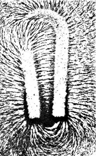
A magnetic field is a vector field that describes the magnetic influence on moving electric charges, electric currents, and magnetic materials. A moving charge in a magnetic field experiences a force perpendicular to its own velocity and to the magnetic field. A permanent magnet's magnetic field pulls on ferromagnetic materials such as iron, and attracts or repels other magnets. In addition, a nonuniform magnetic field exerts minuscule forces on "nonmagnetic" materials by three other magnetic effects: paramagnetism, diamagnetism, and antiferromagnetism, although these forces are usually so small they can only be detected by laboratory equipment. Magnetic fields surround magnetized materials, electric currents, and electric fields varying in time. Since both strength and direction of a magnetic field may vary with location, it is described mathematically by a function assigning a vector to each point of space, called a vector field.
An electric motor is an electrical machine that converts electrical energy into mechanical energy. Most electric motors operate through the interaction between the motor's magnetic field and electric current in a wire winding to generate force in the form of torque applied on the motor's shaft. An electric generator is mechanically identical to an electric motor, but operates in reverse, converting mechanical energy into electrical energy.
An induction motor or asynchronous motor is an AC electric motor in which the electric current in the rotor that produces torque is obtained by electromagnetic induction from the magnetic field of the stator winding. An induction motor therefore needs no electrical connections to the rotor. An induction motor's rotor can be either wound type or squirrel-cage type.
A Newtonian fluid is a fluid in which the viscous stresses arising from its flow are at every point linearly correlated to the local strain rate — the rate of change of its deformation over time. Stresses are proportional to the rate of change of the fluid's velocity vector.
A synchronous electric motor is an AC electric motor in which, at steady state, the rotation of the shaft is synchronized with the frequency of the supply current; the rotation period is exactly equal to an integral number of AC cycles. Synchronous motors use electromagnets as the stator of the motor which create a magnetic field that rotates in time with the oscillations of the current. The rotor with permanent magnets or electromagnets turns in step with the stator field at the same rate and as a result, provides the second synchronized rotating magnet field. A synchronous motor is termed doubly fed if it is supplied with independently excited multiphase AC electromagnets on both the rotor and stator.
A brushless DC electric motor (BLDC), also known as an electronically commutated motor, is a synchronous motor using a direct current (DC) electric power supply. It uses an electronic controller to switch DC currents to the motor windings producing magnetic fields that effectively rotate in space and which the permanent magnet rotor follows. The controller adjusts the phase and amplitude of the DC current pulses to control the speed and torque of the motor. This control system is an alternative to the mechanical commutator (brushes) used in many conventional electric motors.
A DC motor is an electrical motor that uses direct current (DC) to produce mechanical force. The most common types rely on magnetic forces produced by currents in the coils. Nearly all types of DC motors have some internal mechanism, either electromechanical or electronic, to periodically change the direction of current in part of the motor.
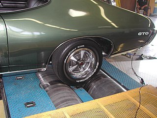
A dynamometer or "dyno" for short, is a device for simultaneously measuring the torque and rotational speed (RPM) of an engine, motor or other rotating prime mover so that its instantaneous power may be calculated, and usually displayed by the dynamometer itself as kW or bhp.
A variable-frequency drive is a type of AC motor drive that controls speed and torque by varying the frequency of the input electricity. Depending on its topology, it controls the associated voltage or current variation.
An AC motor is an electric motor driven by an alternating current (AC). The AC motor commonly consists of two basic parts, an outside stator having coils supplied with alternating current to produce a rotating magnetic field, and an inside rotor attached to the output shaft producing a second rotating magnetic field. The rotor magnetic field may be produced by permanent magnets, reluctance saliency, or DC or AC electrical windings.
Direct torque control (DTC) is one method used in variable-frequency drives to control the torque of three-phase AC electric motors. This involves calculating an estimate of the motor's magnetic flux and torque based on the measured voltage and current of the motor.
Doubly fed electric machines, also slip-ring generators, are electric motors or electric generators, where both the field magnet windings and armature windings are separately connected to equipment outside the machine.
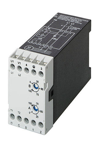
A motor soft starter is a device used with AC electrical motors to temporarily reduce the load and torque in the powertrain and electric current surge of the motor during start-up. This reduces the mechanical stress on the motor and shaft, as well as the electrodynamic stresses on the attached power cables and electrical distribution network, extending the lifespan of the system.
An induction generator or asynchronous generator is a type of alternating current (AC) electrical generator that uses the principles of induction motors to produce electric power. Induction generators operate by mechanically turning their rotors faster than synchronous speed. A regular AC induction motor usually can be used as a generator, without any internal modifications. Because they can recover energy with relatively simple controls, induction generators are useful in applications such as mini hydro power plants, wind turbines, or in reducing high-pressure gas streams to lower pressure.
The rotor is a moving component of an electromagnetic system in the electric motor, electric generator, or alternator. Its rotation is due to the interaction between the windings and magnetic fields which produces a torque around the rotor's axis.
Ward Leonard control, also known as the Ward Leonard drive system, was a widely used DC motor speed control system introduced by Harry Ward Leonard in 1891. In the early 1900s, the control system of Ward Leonard was adopted by the U.S. Navy and also used in passenger lifts of large mines. It also provided a solution to a moving sidewalk at the Paris Exposition of 1900, where many others had failed to operate properly. It was applied to railway locomotives used in World War I, and was used in anti-aircraft radars in World War II. Connected to automatic anti-aircraft gun directors, the tracking motion in two dimensions had to be extremely smooth and precise. The MIT Radiation Laboratory selected Ward-Leonard to equip the famous radar SCR-584 in 1942. The Ward Leonard control system was widely used for elevators until thyristor drives became available in the 1980s, because it offered smooth speed control and consistent torque. Many Ward Leonard control systems and variations on them remain in use.
In electrical engineering, electric machine is a general term for machines using electromagnetic forces, such as electric motors, electric generators, and others. They are electromechanical energy converters: an electric motor converts electricity to mechanical power while an electric generator converts mechanical power to electricity. The moving parts in a machine can be rotating or linear. Besides motors and generators, a third category often included is transformers, which although they do not have any moving parts are also energy converters, changing the voltage level of an alternating current.
DC injection braking is a method of slowing AC electric motors. Direct Current is injected into the winding of the AC motor after the AC voltage is disconnected, providing braking force to the rotor.
An armature controlled DC motor is a direct current (DC) motor that uses a permanent magnet driven by the armature coils only.
↑ Bose, Bimal K. (June 2009). "The Past, Present, and Future of Power Electronics". IEEE Industrial Electronics Magazine. 3 (2): 11. doi:10.1109/MIE.2009.932709.
↑ Rafiq, Md Abdur (2006). "Fast Speed Response Field-Orientation Control of Induction Motor Drive with Adaptive Neural Integator". Istanbul University Journal of Electrical & Electronics Engineering. 6 (2): 229.
1 2 3 Drury, Bill (2009). The Control Techniques Drives and Controls Handbook (2nded.). Stevenage, Herts, UK: Institution of Engineering and Technology. p.xxx. ISBN978-1-84919-101-2.
↑ Bose, Bimal K. (2006). Power Electronics and Motor Drives: Advances and Trends. Amsterdam: Academic. p.22. ISBN978-0-12-088405-6.
↑ Gabriel, R.; Leonhard, W.; Nordby, C.J. (March–April 1980). "Field Oriented Control of Standard AC Motors Using Microprocessors". IEEE Transactions on Industry Applications. IA-16 (2): 188. doi:10.1109/tia.1980.4503770. S2CID14562471.
↑ Park, Robert (1929). "Two-reaction theory of synchronous machines generalized method of analysis-part I". Transactions of the American Institute of Electrical Engineers. 48 (3): 716–730. doi:10.1109/t-aiee.1929.5055275. S2CID51643456.
This page is based on this Wikipedia article Text is available under the CC BY-SA 4.0 license; additional terms may apply. Images, videos and audio are available under their respective licenses.