
An electric motor is an electrical machine that converts electrical energy into mechanical energy. Most electric motors operate through the interaction between the motor's magnetic field and electric current in a wire winding to generate force in the form of torque applied on the motor's shaft. An electric generator is mechanically identical to an electric motor, but operates in reverse, converting mechanical energy into electrical energy.

An alternator is an electrical generator that converts mechanical energy to electrical energy in the form of alternating current. For reasons of cost and simplicity, most alternators use a rotating magnetic field with a stationary armature. Occasionally, a linear alternator or a rotating armature with a stationary magnetic field is used. In principle, any AC electrical generator can be called an alternator, but usually the term refers to small rotating machines driven by automotive and other internal combustion engines.

An induction motor or asynchronous motor is an AC electric motor in which the electric current in the rotor that produces torque is obtained by electromagnetic induction from the magnetic field of the stator winding. An induction motor therefore needs no electrical connections to the rotor. An induction motor's rotor can be either wound type or squirrel-cage type.

Two-terminal components and electrical networks can be connected in series or parallel. The resulting electrical network will have two terminals, and itself can participate in a series or parallel topology. Whether a two-terminal "object" is an electrical component or an electrical network is a matter of perspective. This article will use "component" to refer to a two-terminal "object" that participates in the series/parallel networks.

A synchronous electric motor is an AC electric motor in which, at steady state, the rotation of the shaft is synchronized with the frequency of the supply current; the rotation period is exactly equal to an integer number of AC cycles. Synchronous motors use electromagnets as the stator of the motor which create a magnetic field that rotates in time with the oscillations of the current. The rotor with permanent magnets or electromagnets turns in step with the stator field at the same rate and as a result, provides the second synchronized rotating magnet field. A synchronous motor is termed doubly fed if it is supplied with independently excited multiphase AC electromagnets on both the rotor and stator.

The utility frequency, (power) line frequency or mains frequency is the nominal frequency of the oscillations of alternating current (AC) in a wide area synchronous grid transmitted from a power station to the end-user. In large parts of the world this is 50 Hz, although in the Americas and parts of Asia it is typically 60 Hz. Current usage by country or region is given in the list of mains electricity by country.
Transconductance, also infrequently called mutual conductance, is the electrical characteristic relating the current through the output of a device to the voltage across the input of a device. Conductance is the reciprocal of resistance.
A motor–generator is a device for converting electrical power to another form. Motor–generator sets are used to convert frequency, voltage, or phase of power. They may also be used to isolate electrical loads from the electrical power supply line. Large motor–generators were widely used to convert industrial amounts of power while smaller motor–generators were used to convert battery power to higher DC voltages.

In electronics, a chopper circuit is any of numerous types of electronic switching devices and circuits used in power control and signal applications. A chopper is a device that converts fixed DC input to a variable DC output voltage directly. Essentially, a chopper is an electronic switch that is used to interrupt one signal under the control of another.
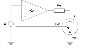
A potentiostat is the electronic hardware required to control a three electrode cell and run most electroanalytical experiments. A Bipotentiostat and polypotentiostat are potentiostats capable of controlling two working electrodes and more than two working electrodes, respectively.

In electrical engineering, a synchronous condenser is a DC-excited synchronous motor, whose shaft is not connected to anything but spins freely. Its purpose is not to convert electric power to mechanical power or vice versa, but to adjust conditions on the electric power transmission grid. Its field is controlled by a voltage regulator to either generate or absorb reactive power as needed to adjust the grid's voltage, or to improve power factor. The condenser’s installation and operation are identical to large electric motors and generators.

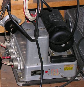
Harry Ward Leonard was an American electrical engineer and inventor. He is best known for his invention, the Ward Leonard motor control system. Equipment based on this invention remained in service into the 21st century.

An amplidyne is an obsolete electromechanical amplifier invented prior to World War II by Ernst Alexanderson. It consists of an electric motor driving a DC generator. The signal to be amplified is applied to the generator's field winding, and its output voltage is an amplified copy of the field current. The amplidyne was used in industry in high power servo and control systems, to amplify low power control signals to control powerful electric motors, for example. It is now mostly obsolete.

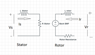
The rotor is a moving component of an electromagnetic system in the electric motor, electric generator, or alternator. Its rotation is due to the interaction between the windings and magnetic fields which produces a torque around the rotor's axis.
A brushed DC electric motor is an internally commutated electric motor designed to be run from a direct current power source and utilizing an electric brush for contact.
Vector control, also called field-oriented control (FOC), is a variable-frequency drive (VFD) control method in which the stator currents of a three-phase AC or brushless DC electric motor are identified as two orthogonal components that can be visualized with a vector. One component defines the magnetic flux of the motor, the other the torque. The control system of the drive calculates the corresponding current component references from the flux and torque references given by the drive's speed control. Typically proportional-integral (PI) controllers are used to keep the measured current components at their reference values. The pulse-width modulation of the variable-frequency drive defines the transistor switching according to the stator voltage references that are the output of the PI current controllers.
A permanent magnet synchronous generator is a generator where the excitation field is provided by a permanent magnet instead of a coil. The term synchronous refers here to the fact that the rotor and magnetic field rotate with the same speed, because the magnetic field is generated through a shaft mounted permanent magnet mechanism and current is induced into the stationary armature.
The motor size constant and motor velocity constant are values used to describe characteristics of electrical motors.
An armature controlled DC motor is a direct current (DC) motor that uses a permanent magnet driven by the armature coils only.
This glossary of electrical and electronics engineering is a list of definitions of terms and concepts related specifically to electrical engineering and electronics engineering. For terms related to engineering in general, see Glossary of engineering.
 Engine room with Ward-Leonard groups for the extraction machines of Winterslag Coal Mine in Genk (Belgium)


