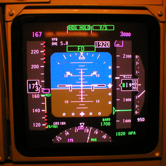
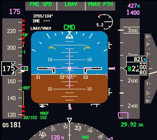
On the flight deck, the display units are the most obvious parts of an EFIS system, and are the features that lead to the term glass cockpit. The display unit that replaces the artificial horizon is called the primary flight display (PFD). If a separate display replaces the HSI, it is called the navigation display. The PFD displays all information critical to flight, including calibrated airspeed, altitude, heading, attitude, vertical speed and yaw. The PFD is designed to improve a pilot's situational awareness by integrating this information into a single display instead of six different analog instruments, reducing the amount of time necessary to monitor the instruments. PFDs also increase situational awareness by alerting the aircrew to unusual or potentially hazardous conditions— for example, low airspeed, high rate of descent— by changing the color or shape of the display or by providing audio alerts.
The names Electronic Attitude Director Indicator and Electronic Horizontal Situation Indicator are used by some manufacturers.[1] However, a simulated ADI is only the centerpiece of the PFD. Additional information is both superimposed on and arranged around this graphic.
Multi-function displays can render a separate navigation display unnecessary. Another option is to use one large screen to show both the PFD and navigation display.
The PFD and navigation display (and multi-function display, where fitted) are often physically identical. The information displayed is determined by the system interfaces where the display units are fitted. Thus, spares holding is simplified: the one display unit can be fitted in any position.
LCD units generate less heat than CRTs; an advantage in a congested instrument panel. They are also lighter, and occupy a lower volume.
Multi-function display (MFD)
The navigation display (ND) of a Boeing 747-400 aircraft
The MFD (multi-function display) displays navigational and weather information from multiple systems. MFDs are most frequently designed as "chart-centric", where the aircrew can overlay different information over a map or chart. Examples of MFD overlay information include the aircraft's current route plan, weather information from either on-board radar or lightning detection sensors or ground-based sensors, e.g., NEXRAD, restricted airspace and aircraft traffic. The MFD can also be used to view other non-overlay type of data (e.g., current route plan) and calculated overlay-type data, e.g., the glide radius of the aircraft, given current location over terrain, winds, and aircraft speed and altitude.
MFDs can also display information about aircraft systems, such as fuel and electrical systems (see EICAS, below). As with the PFD, the MFD can change the color or shape of the data to alert the aircrew to hazardous situations.
Engine indications and crew alerting system (EICAS) / electronic centralized aircraft monitoring (ECAM)
EICAS (Engine Indications and Crew Alerting System) displays information about the aircraft's systems, including its fuel, electrical and propulsion systems (engines). EICAS displays are often designed to mimic traditional round gauges while also supplying digital readouts of the parameters.
EICAS improves situational awareness by allowing the aircrew to view complex information in a graphical format and also by alerting the crew to unusual or hazardous situations. For example, if an engine begins to lose oil pressure, the EICAS might sound an alert, switch the display to the page with the oil system information and outline the low oil pressure data with a red box. Unlike traditional round gauges, many levels of warnings and alarms can be set. Proper care must be taken when designing EICAS to ensure that the aircrew are always provided with the most important information and not overloaded with warnings or alarms.
ECAM is a similar system used by Airbus, which in addition to providing EICAS functions also recommend remedial action.
A 737NG EICAS after landing, showing outside air temperature, N1 RPM, exhaust gas temperature, N2 RPM, fuel flow, fuel used, fuel in the tanks, oil pressure, oil temperature, oil quantity, engine vibration, hydraulic pressure and hydraulic quantity
Control panels
EFIS provides pilots with controls that select display range and mode (for example, map or compass rose) and enter data (such as selected heading).
Where other equipment uses pilot inputs, data buses broadcast the pilot's selections so that the pilot need only enter the selection once. For example, the pilot selects the desired level-off altitude on a control unit. The EFIS repeats this selected altitude on the PFD, and by comparing it with the actual altitude (from the air data computer) generates an altitude error display. This same altitude selection is used by the automatic flight control system to level off, and by the altitude alerting system to provide appropriate warnings.
Data processors
The EFIS visual display is produced by the symbol generator. This receives data inputs from the pilot, signals from sensors, and EFIS format selections made by the pilot. The symbol generator can go by other names, such as display processing computer, display electronics unit, etc.
The symbol generator does more than generate symbols. It has (at the least) monitoring facilities, a graphics generator and a display driver.[2] Inputs from sensors and controls arrive via data buses, and are checked for validity. The required computations are performed, and the graphics generator and display driver produce the inputs to the display units.
Capabilities
Like personal computers, flight instrument systems need power-on-self-test facilities and continuous self-monitoring. Flight instrument systems, however, need additional monitoring capabilities:
Input validation— verify that each sensor is providing valid data
Data comparison— cross check inputs from duplicated sensors
Display monitoring— detect failures within the instrument system
Former practice
Traditional (electromechanical) displays are equipped with synchro mechanisms that transmit the pitch, roll, and heading shown on the captain and first officer's instruments to an instrument comparator. The comparator warns of excessive differences between the Captain and First Officer displays. Even a fault as far downstream[3] as a jam in, say, the roll mechanism of an ADI triggers a comparator warning. The instrument comparator thus provides both comparator monitoring and display monitoring.
Comparator monitoring
With EFIS, the comparator function is simple: Is roll data (bank angle) from sensor 1 the same as roll data from sensor 2? If not, display a warning caption (such as CHECK ROLL) on both PFDs. Comparison monitors give warnings for airspeed, pitch, roll, and altitude indications. More advanced EFIS systems have more comparator monitors.
Display monitoring
In this technique, each symbol generator contains two display monitoring channels. One channel, the internal, samples the output from its own symbol generator to the display unit and computes, for example, what roll attitude should produce that indication. This computed roll attitude is then compared with the roll attitude input to the symbol generator from the INS or AHRS. Any difference has probably been introduced by faulty processing, and triggers a warning on the relevant display.
The external monitoring channel carries out the same check on the symbol generator on the other side of the flight deck: the Captain's symbol generator checks the First Officer's, the First Officer's checks the Captain's. Whichever symbol generator detects a fault, puts up a warning on its own display.
The external monitoring channel also checks sensor inputs (to the symbol generator) for reasonableness. A spurious input, such as a radio height greater than the radio altimeter's maximum, results in a warning.
Human factors
Clutter
At various stages of a flight, a pilot needs different combinations of data. Ideally, the avionics only show the data in use—but an electromechanical instrument must be in view all the time. To improve display clarity, ADIs and HSIs use intricate mechanisms to remove superfluous indications temporarily—e.g., removing the glide slope scale when the pilot doesn't need it.
Under normal conditions, an EFIS might not display some indications, e.g., engine vibration. Only when some parameter exceeds its limits does the system display the reading. In similar fashion, EFIS is programmed to show the glideslope scale and pointer only during an ILS approach.
In the case of an input failure, an electromechanical instrument adds yet another indicator—typically, a bar drops across the erroneous data. EFIS, on the other hand, removes invalid data from the display and substitutes an appropriate warning.
A de-clutter mode activates automatically when circumstances require the pilot's attention for a specific item. For example, if the aircraft pitches up or down beyond a specified limit—usually 30 to 60 degrees—the attitude indicator de-clutters other items from sight until the pilot brings the pitch to an acceptable level. This helps the pilot focus on the most important tasks.
Color
Traditional instruments have long used color, but lack the ability to change a color to indicate some change in condition. The electronic display technology of EFIS has no such restriction and uses color widely. For example, as an aircraft approaches the glide slope, a blue caption can indicate glide slope is armed, and capture might change the color to green. Typical EFIS systems color code the navigation needles to reflect the type of navigation. Green needles indicate ground-based navigation, such as VORs, Localizers and ILS systems. Magenta needles indicate GPS navigation.
Advantages
EFIS provides versatility by avoiding some physical limitations of traditional instruments. A pilot can switch the same display that shows a course deviation indicator to show the planned track provided by an area navigation or flight management system. Pilots can choose to superimpose the weather radar picture on the displayed route.
The flexibility afforded by software modifications minimises the costs of responding to new aircraft regulations and equipment. Software updates can update an EFIS system to extend its capabilities. Updates introduced in the 1990s included the ground proximity warning system and traffic collision avoidance system.
A degree of redundancy is available even with the simple two-screen EFIS installation. Should the PFD fail, transfer switching repositions its vital information to the screen normally occupied by the navigation display.
Advances in EFIS
In the late 1980s, EFIS became standard equipment on most Boeing and Airbusairliners, and many business aircraft adopted EFIS in the 1990s.
Several EFIS manufacturers have focused on the experimental aircraft market, producing EFIS and EICAS systems for as little as US$1,000-2000. The low cost is possible because of steep drops in the price of sensors and displays, and equipment for experimental aircraft doesn't require expensive Federal Aviation Administration certification. This latter point restricts their use to experimental aircraft and certain other aircraft categories, depending on local regulations. Uncertified EFIS systems are also found in Light-sport aircraft, including factory built, microlight, and ultralight aircraft. These systems can be fitted to certified aircraft in some cases as secondary or backup systems depending on local aviation rules.
↑ Primary flight display and navigation display are the names used in the Federal Aviation Administration Advisory Circulars and also in ARINC Specification 725
Avionics are the electronic systems used on aircraft, artificial satellites, and spacecraft. Avionic systems include communications, navigation, the display and management of multiple systems, and the hundreds of systems that are fitted to aircraft to perform individual functions. These can be as simple as a searchlight for a police helicopter or as complicated as the tactical system for an airborne early warning platform.
Flight instruments are the instruments in the cockpit of an aircraft that provide the pilot with data about the flight situation of that aircraft, such as altitude, airspeed, vertical speed, heading and much more other crucial information in flight. They improve safety by allowing the pilot to fly the aircraft in level flight, and make turns, without a reference outside the aircraft such as the horizon. Visual flight rules (VFR) require an airspeed indicator, an altimeter, and a compass or other suitable magnetic direction indicator. Instrument flight rules (IFR) additionally require a gyroscopic pitch-bank, direction and rate of turn indicator, plus a slip-skid indicator, adjustable altimeter, and a clock. Flight into instrument meteorological conditions (IMC) require radio navigation instruments for precise takeoffs and landings.
A cockpit or flight deck is the area, usually near the front of an aircraft or spacecraft, from which a pilot controls the aircraft.
The attitude indicator (AI), formerly known as the gyro horizon or artificial horizon, is a flight instrument that informs the pilot of the aircraft orientation relative to Earth's horizon, and gives an immediate indication of the smallest orientation change. The miniature aircraft and horizon bar mimic the relationship of the aircraft relative to the actual horizon. It is a primary instrument for flight in instrument meteorological conditions.
An autopilot is a system used to control the trajectory of an aircraft, marine craft or spacecraft without requiring constant manual control by a human operator. Autopilots do not replace human operators. Instead, the autopilot assists the operator's control of the vehicle, allowing the operator to focus on broader aspects of operations.
A head-up display, also known as a HUD, is any transparent display that presents data without requiring users to look away from their usual viewpoints. The origin of the name stems from a pilot being able to view information with the head positioned "up" and looking forward, instead of angled down looking at lower instruments. A HUD also has the advantage that the pilot's eyes do not need to refocus to view the outside after looking at the optically nearer instruments.
A glass cockpit is an aircraft cockpit that features electronic (digital) flight instrument displays, typically large LCD screens, rather than the traditional style of analog dials and gauges. While a traditional cockpit relies on numerous mechanical gauges to display information, a glass cockpit uses several multi-function displays driven by flight management systems, that can be adjusted to display flight information as needed. This simplifies aircraft operation and navigation and allows pilots to focus only on the most pertinent information. They are also popular with airline companies as they usually eliminate the need for a flight engineer, saving costs. In recent years the technology has also become widely available in small aircraft.
A multifunction display (MFD) is a small-screen surrounded by multiple soft keys that can be used to display information to the user in numerous configurable ways. MFDs originated in aviation, first in military aircraft, and later were adopted by commercial aircraft, general aviation, automotive use, and shipboard use.
An engine-indicating and crew-alerting system (EICAS) is an integrated system used in modern aircraft to provide aircraft flight crew with instrumentation and crew annunciations for aircraft engines and other systems. On EICAS equipped aircraft the "recommended remedial action" is called a checklist.
An attitude and heading reference system (AHRS) consists of sensors on three axes that provide attitude information for aircraft, including roll, pitch and yaw. These are sometimes referred to as MARG sensors and consist of either solid-state or microelectromechanical systems (MEMS) gyroscopes, accelerometers and magnetometers. They are designed to replace traditional mechanical gyroscopic flight instruments.
The Garmin G1000 is an integrated flight instrument system typically composed of two display units, one serving as a primary flight display, and one as a multi-function display. Manufactured by Garmin Aviation, it serves as a replacement for most conventional flight instruments and avionics.
A primary flight display or PFD is a modern aircraft instrument dedicated to flight information. Much like multi-function displays, primary flight displays are built around a Liquid-crystal display or CRT display device. Representations of older six pack or "steam gauge" instruments are combined on one compact display, simplifying pilot workflow and streamlining cockpit layouts.
A flight management system (FMS) is a fundamental component of a modern airliner's avionics. An FMS is a specialized computer system that automates a wide variety of in-flight tasks, reducing the workload on the flight crew to the point that modern civilian aircraft no longer carry flight engineers or navigators. A primary function is in-flight management of the flight plan. Using various sensors to determine the aircraft's position, the FMS can guide the aircraft along the flight plan. From the cockpit, the FMS is normally controlled through a Control Display Unit (CDU) which incorporates a small screen and keyboard or touchscreen. The FMS sends the flight plan for display to the Electronic Flight Instrument System (EFIS), Navigation Display (ND), or Multifunction Display (MFD). The FMS can be summarised as being a dual system consisting of the Flight Management Computer (FMC), CDU and a cross talk bus.
A synthetic vision system (SVS) is a computer-mediated reality system for aerial vehicles, that uses 3D to provide pilots with clear and intuitive means of understanding their flying environment.
An Air Data Inertial Reference Unit (ADIRU) is a key component of the integrated Air Data Inertial Reference System (ADIRS), which supplies air data and inertial reference information to the pilots' electronic flight instrument system displays as well as other systems on the aircraft such as the engines, autopilot, aircraft flight control system and landing gear systems. An ADIRU acts as a single, fault tolerant source of navigational data for both pilots of an aircraft. It may be complemented by a secondary attitude air data reference unit (SAARU), as in the Boeing 777 design.
An electronic centralised aircraft monitoring (ECAM) is a system that monitors aircraft functions and relays them to the pilots. It also produces messages detailing failures and in certain cases, lists procedures to undertake to correct the problem.
Chelton Flight Systems designs and manufactures advanced avionics and flight controls. Based in Boise, Idaho, Chelton Flight Systems originally started out as Sierra Flight Systems. The company was co-founded by Gordon Pratt and Rick Price in 1997. It is part of Genesys Aerosystems since 2014.
Avidyne Entegra is an integrated aircraft instrumentation system, produced by Avidyne Corporation, consisting of a primary flight display (PFD), and multi-function display (MFD). Cirrus became the first customer of the Entegra system and began offering it on the SR20 and SR22 aircraft in 2003 as the first integrated flight deck for light general aviation (GA). The original Entegra system was designed to use third-party components such as a GPS from Garmin and an autopilot system from S-TEC Corporation.
L-3 SmartDeck - is a fully integrated cockpit system originally developed by L-3 Avionics Systems. and acquired in 2010 by Esterline CMC Electronics through an exclusive licensing agreement.
Alitalia Flight 404 (AZ404/AZA404) was an international passenger flight scheduled to fly from Linate Airport in Milan, Italy, to Zürich Airport in Zürich, Switzerland, which crashed on 14 November 1990. The Douglas DC-9-32, operated by Alitalia, crashed into the woodlands of Weiach as it approached Zurich Airport, killing all 46 people on board.
This page is based on this Wikipedia article Text is available under the CC BY-SA 4.0 license; additional terms may apply. Images, videos and audio are available under their respective licenses.