Executable UML

Last updated

Executable UML (xtUML or xUML) is both a software development method and a highly abstract software language. It was described for the first time in 2002 in the book "Executable UML: A Foundation for Model-Driven Architecture". [1] The language "combines a subset of the UML (Unified Modeling Language) graphical notation with executable semantics and timing rules." [2] The Executable UML method is the successor to the Shlaer–Mellor method. [3]

Contents

Executable UML models "can be run, tested, debugged, and measured for performance.", [4] and can be compiled into a less abstract programming language to target a specific implementation. [5] Executable UML supports model-driven architecture (MDA) through specification of platform-independent models, and the compilation of the platform-independent models into platform-specific models. [6] [7]

Overview

Executable UML is a higher level of abstraction than third-generation programming languages. This allows developers to develop at the level of abstraction of the application. [8] The Executable UML aims for separation of concerns. This is supposed to increase ease of reuse and to lower the cost of software development. This also enables Executable UML domains to be cross-platform. That means it is not tied to any specific programming language, platform or technology.

Executable UML also allows for translation of platform-independent models (PIM) into platform-specific models (PSM). The Executable UML method enables valuing the model as intellectual property, since the model is a fully executable solution for the problem space.

Actions are specified in action language. This means that the automatic generation of implementation code from Executable UML models can be output in an optimized form.

Executable UML is intended to serve as executable code as well as documentation. The models are a graphical, executable specification of the problem space that is compiled into a target implementation. They are also intended to be human-readable.

Executable UML building blocks

A system is composed of multiple subject matters, known as domains in Executable UML terms. Executable UML is used to model a domain at the level of abstraction of its subject matter independent of implementation concerns. The resulting domain model is represented by the following elements:

Domain chart

Executable UML requires identification of the domains (also known as: aspects [9] or concerns) of the system. "Each domain is an autonomous world inhabited by conceptual entities" [10] Each domain can be modeled independent of the other domains in the system, enabling a separation of concerns. As an example, domains for an automated teller system may include the following:

The separation of concerns enables each domain to be developed and verified independently of the other domains in the system by the respective domain experts.

The connections between domains are called bridges. "A bridge is a layering dependency between domains". [11] This means that the domains can place requirements upon other domains. It is recommended that bridges are agreed upon by the different domain experts.

A domain can be marked as realized to indicate that the domain exists and does not need to be modeled. For example, a data access domain that uses a MySQL database would be marked as realized.

Class diagram

Conceptual entities, such as tangible things, roles, incidents, interactions, and specifications, specific to the domain being modeled are abstracted into classes. Classes can have attributes and operations.

The relationships between these classes will be indicated with associations and generalizations. An association may require further abstraction as an Association Class.

Constraints on the class diagram can be written in both Action Language and Object Constraint Language (OCL).

The Executable UML method limits the UML elements that can be used in an Executable UML class diagram.

An Executable UML class diagram is meant to expose information about the domain. Too much complexity in the statechart diagrams is a good indicator that the class diagram should be reworked.

Statechart diagram

Classes have lifecycles which are modeled in Executable UML with a statechart diagram. The statechart diagram defines the states, transitions, events, and procedures that define a class' behaviour.

Each state has only one procedure that is executed upon entry into that state. A procedure is composed of actions, which are specified in an action language.

Action language

The class and state models by themselves can only provide a static view of the domain. In order to have an executable model, there must be a way to create class instances, establish associations, perform operations on attributes, call state events, etc. In Executable UML, this is done using an action language that conforms to the UML Action Semantics.

Action Semantics was added to the UML specification in 2001. The Action Semantics RFP was based on previous work in action languages supporting the Shlaer–Mellor method. Existing action languages are Object Action Language (OAL), Shlaer–Mellor Action Language (SMALL), Action Specification Language (ASL), Model Action Specification Language (MASL), [12] That Action Language (TALL), Starr's Concise Relational Action Language (SCRALL), Platform-independent Action Language (PAL) and PathMATE Action Language (PAL). SCRALL is the only one that is a graphical action language.

Model testing and execution

Once a domain is modeled, it can be tested independent of the target implementation by executing the model. Each domain can be verified and validated independent of any other domain. This allows errors detected to be associated with the domain and independent of other system concerns.

Verification will involve such things as human review of the models, performed by experts in the relevant domain, and automated checking of the Executable UML semantics. i.e., checking that the Executable UML model complies with the Executable UML metamodel.

Validation will typically involve use of an Executable UML tool to execute the model. The execution can occur either before or after model compilation.

Model compilation

In order to support execution on the target implementation, the domain model must be translated into a less abstract form. This translation process is called model compilation. Most model compilers target a known programming language, because this allows reuse of existing compiler technologies.

Optimizing the domain models for target implementation reasons will reduce the level of abstraction, adversely affect domain independence, and increase the cost of reuse. In executable UML, optimizations are done by the model compiler either automatically or through marking. Marking allows specific model elements to be targeted for specific lower-level implementations, and allows for broader architectural decisions, such as specifying that collections of objects should be implemented as a doubly linked list.

In MDA terms, the model compiler creates the PSM. The separation between the PIM and PSM in Executable UML disables the ability to round-trip engineer the model, and deters modifications to the PSM. [13]

Executable UML key aspects

Executable UML defines execution semantics for a subset of the UML. Key aspects of the Executable UML subset include the following:

fUML and ALF

The Object Management Group has standardized the Foundational UML (fUML), which was strongly influenced by Executable UML.

Action Language for Foundational UML (ALF), [15] is a standard action language specification by the Object Management Group.

See also

Publications

Related Research Articles

<span class="mw-page-title-main">Meta-Object Facility</span> Standard of Object Management Group

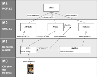
The Meta-Object Facility (MOF) is an Object Management Group (OMG) standard for model-driven engineering. Its purpose is to provide a type system for entities in the CORBA architecture and a set of interfaces through which those types can be created and manipulated. The official reference page may be found at OMG's website.

<span class="mw-page-title-main">State diagram</span> Diagram of behavior of finite state systems

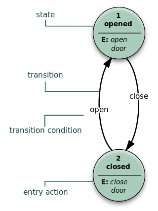
A state diagram is a type of diagram used in computer science and related fields to describe the behavior of systems. State diagrams require that the system described is composed of a finite number of states; sometimes, this is indeed the case, while at other times this is a reasonable abstraction. Many forms of state diagrams exist, which differ slightly and have different semantics.

A modeling language is any artificial language that can be used to express information or knowledge or systems in a structure that is defined by a consistent set of rules. The rules are used for interpretation of the meaning of components in the structure Programing language.

Model Driven Architecture (MDA) is a software design approach for the development of software systems. It provides a set of guidelines for the structuring of specifications, which are expressed as models. Model Driven Architecture is a kind of domain engineering, and supports model-driven engineering of software systems. It was launched by the Object Management Group (OMG) in 2001.

<span class="mw-page-title-main">Entity–relationship model</span> Model or diagram describing interrelated things

An entity–relationship model describes interrelated things of interest in a specific domain of knowledge. A basic ER model is composed of entity types and specifies relationships that can exist between entities.

<span class="mw-page-title-main">Metamodeling</span> Concept of software engineering

A metamodel or surrogate model is a model of a model, and metamodeling is the process of generating such metamodels. Thus metamodeling or meta-modeling is the analysis, construction and development of the frames, rules, constraints, models and theories applicable and useful for modeling a predefined class of problems. As its name implies, this concept applies the notions of meta- and modeling in software engineering and systems engineering. Metamodels are of many types and have diverse applications.

A UML tool is a software application that supports some or all of the notation and semantics associated with the Unified Modeling Language (UML), which is the industry standard general-purpose modeling language for software engineering.

Domain-specific modeling (DSM) is a software engineering methodology for designing and developing systems, such as computer software. It involves systematic use of a domain-specific language to represent the various facets of a system.

The Shlaer–Mellor method, also known as object-oriented systems analysis (OOSA) or object-oriented analysis (OOA) is an object-oriented software development methodology introduced by Sally Shlaer and Stephen Mellor in 1988. The method makes the documented analysis so precise that it is possible to implement the analysis model directly by translation to the target architecture, rather than by elaborating model changes through a series of more platform-specific models. In the new millennium the Shlaer–Mellor method has migrated to the UML notation, becoming Executable UML.

<span class="mw-page-title-main">Class diagram</span> Type of static structure diagram

In software engineering, a class diagram in the Unified Modeling Language (UML) is a type of static structure diagram that describes the structure of a system by showing the system's classes, their attributes, operations, and the relationships among objects.

Object-oriented analysis and design (OOAD) is a technical approach for analyzing and designing an application, system, or business by applying object-oriented programming, as well as using visual modeling throughout the software development process to guide stakeholder communication and product quality.

Glossary of Unified Modeling Language (UML) terms provides a compilation of terminology used in all versions of UML, along with their definitions. Any notable distinctions that may exist between versions are noted with the individual entry it applies to.

Model-driven engineering (MDE) is a software development methodology that focuses on creating and exploiting domain models, which are conceptual models of all the topics related to a specific problem. Hence, it highlights and aims at abstract representations of the knowledge and activities that govern a particular application domain, rather than the computing concepts.

<span class="mw-page-title-main">MagicDraw</span> Systems modelling software

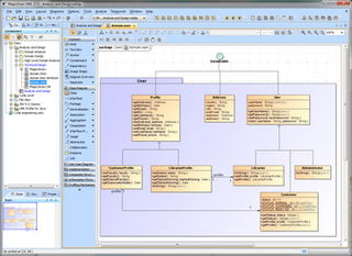
MagicDraw is a proprietary visual UML, SysML, BPMN, and UPDM modeling tool with team collaboration support.

Stephen J. Mellor is an American computer scientist, developer of the Ward–Mellor method for real-time computing, the Shlaer–Mellor method, and Executable UML, and signatory to the Agile Manifesto.

UML state machine, also known as UML statechart, is an extension of the mathematical concept of a finite automaton in computer science applications as expressed in the Unified Modeling Language (UML) notation.

<span class="mw-page-title-main">Applications of UML</span>

UML is a modeling language used by software developers. UML can be used to develop diagrams and provide users (programmers) with ready-to-use, expressive modeling examples. Some UML tools generate program language code from UML. UML can be used for modeling a system independent of a platform language. UML is a graphical language for visualizing, specifying, constructing, and documenting information about software-intensive systems. UML gives a standard way to write a system model, covering conceptual ideas. With an understanding of modeling, the use and application of UML can make the software development process more efficient.

<span class="mw-page-title-main">Sally Shlaer</span> American computer scientist

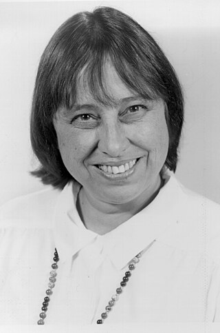
Sally hashim Shlaer was an American mathematician, software engineer and methodologist, known as co-developer of the 1980s Shlaer–Mellor method for software development.

<span class="mw-page-title-main">Interaction Flow Modeling Language</span>

The Interaction Flow Modeling Language (IFML) is a standardized modeling language in the field of software engineering. IFML includes a set of graphic notations to create visual models of user interactions and front-end behavior in software systems.

<span class="mw-page-title-main">Enterprise Architect (software)</span> Visual modeling and design tool

Sparx Systems Enterprise Architect is a visual modeling and design tool based on the OMG UML. The platform supports: the design and construction of software systems; modeling business processes; and modeling industry based domains. It is used by businesses and organizations to not only model the architecture of their systems, but to process the implementation of these models across the full application development life-cycle.

References

  1. Mellor and Balcer 2002
  2. Starr 2002, p. 3.
  3. G. O'Keefe (2006) "Dynamic Logic Semantics for UML Consistency" in: Model-Driven Architecture - Foundations and Applications: Second European Conference, ECMDA-FA 2006, Bilbao, Spain, July 10–13, 2006, Proceedings. Arend Rensink eds. p. 124
  4. Starr 2002, p. 3.
  5. Mellor and Balcer 2002, section 1.4.
  6. Mellor and Balcer 2002, section 1.5.
  7. Raistrick et al. 2004, sections 2.3.3 and 2.3.4.
  8. Mellor and Balcer 2002, section 1.1.
  9. Mellor and Balcer 2002, section 3.4.
  10. Mellor and Balcer 2002, p. 14.
  11. Mellor and Balcer 2002, p. 35.
  12. "MASL is a Shlaer-Mellor dialect action language and structural modeling language.: xtuml/masl". xtUML. 27 December 2018. Retrieved 26 October 2019.
  13. Mellor and Balcer 2002, chapter 9.
  14. Mellor and Balcer 2002, p. xxx.
  15. "Action Language for Foundational UML™ (ALF™)". www.omg.org. Retrieved 2016-12-21.