Flame detector

Last updated

A flame detector is a sensor designed to detect and respond to the presence of a flame or fire, allowing flame detection. Responses to a detected flame depend on the installation, but can include sounding an alarm, deactivating a fuel line (such as a propane or a natural gas line), and activating a fire suppression system. When used in applications such as industrial furnaces, their role is to provide confirmation that the furnace is working properly; it can be used to turn off the ignition system though in many cases they take no direct action beyond notifying the operator or control system. A flame detector can often respond faster and more accurately than a smoke or heat detector due to the mechanisms it uses to detect the flame. [1] [2]

Contents

Optical flame detectors

Flame detector type regions Vlamdetectie spectrum.jpg
Flame detector type regions

Ultraviolet detector

Ultraviolet (UV) detectors work by detecting the UV radiation emitted at the instant of ignition. While capable of detecting fires and explosions within 3–4 milliseconds, a time delay of 2–3 seconds is often included to minimize false alarms which can be triggered by other UV sources such as lightning, arc welding, radiation, and sunlight. UV detectors typically operate with wavelengths shorter than 300  nm to minimize the effects of natural background radiation. The solar blind UV wavelength band is also easily blinded by oily contaminants.

Near IR array

Near infrared (IR) array flame detectors (0.7 to 1.1 μm), also known as visual flame detectors, employ flame recognition technology to confirm fire by analyzing near IR radiation using a charge-coupled device (CCD). A near infrared (IR) sensor is especially able to monitor flame phenomena, without too much hindrance from water and water vapour. Pyroelectric sensors operating at this wavelength can be relatively cheap. Multiple channel or pixel array sensors monitoring flames in the near IR band are arguably the most reliable technologies available for detection of fires. Light emission from a fire forms an image of the flame at a particular instant. Digital image processing can be utilized to recognize flames through analysis of the video created from the near IR images.

Infrared

Infrared (IR) or wideband infrared (1.1 μm and higher) flame detectors monitor the infrared spectral band for specific patterns given off by hot gases. These are sensed using a specialized fire-fighting thermal imaging camera (TIC), a type of thermographic camera. False alarms can be caused by other hot surfaces and background thermal radiation in the area. Water on the detector's lens will greatly reduce the accuracy of the detector, as will exposure to direct sunlight. A special frequency range is 4.3 to 4.4 μm. This is a resonance frequency of CO2. During burning of a hydrocarbon (for example, wood or fossil fuels such as oil and natural gas) much heat and CO2 is released. The hot CO2 emits much energy at its resonance frequency of 4.3 μm. This causes a peak in the total radiation emission and can be well detected. Moreover, the "cold" CO2 in the air is taking care that the sunlight and other IR radiation is filtered. This makes the sensor in this frequency "solar blind"; however, sensitivity is reduced by sunlight. By observing the flicker frequency of a fire (1 to 20 Hz) the detector is made less sensitive to false alarms caused by heat radiation, for example caused by hot machinery.

A severe disadvantage is that almost all radiation can be absorbed by water or water vapour; this is particularly valid for infrared flame detection in the 4.3 to 4.4 μm region. From approx. 3.5 μm and higher the absorption by water or ice is practically 100%. This makes infrared sensors for use in outdoor applications very unresponsive to fires. The biggest problem is our ignorance; some infrared detectors have an (automatic) detector window self test, but this self test only monitors the occurrence of water or ice on the detector window.

A salt film is also harmful, because salt absorbs water. However, water vapour, fog or light rain also makes the sensor almost blind, without the user knowing. The cause is similar to what a fire fighter does if he approaches a hot fire: he protects himself by means of a water vapour screen against the enormous infrared heat radiation. The presence of water vapor, fog, or light rain will then also "protect" the monitor causing it to not see the fire. Visible light will, however be transmitted through the water vapour screen, as can easily been seen by the fact that a human can still see the flames through the water vapour screen.

The usual response time of an IR detector is 3–5 seconds.

Infrared thermal cameras

MWIR infrared (IR) cameras can be used to detect heat and with particular algorithms can detect hot-spots within a scene as well as flames for both detection and prevention of fire and risks of fire. These cameras can be used in complete darkness and operate both inside and outside.

UV/IR

These detectors are sensitive to both UV and IR wavelengths, and detect flame by comparing the threshold signal of both ranges. This helps minimize false alarms.

IR/IR flame detection

Dual IR (IR/IR) flame detectors compare the threshold signal in two infrared ranges. Often one sensor looks at the 4.4 micrometer carbon dioxide (CO2), while the other sensor looks at a reference frequency. Sensing the CO2 emission is appropriate for hydrocarbon fuels; for non-carbon based fuels, e.g., hydrogen, the broadband water bands are sensed.

IR3 flame detection

Multi-infrared detectors make use of algorithms to suppress the effects of background radiation (blackbody radiation), again sensitivity is reduced by this radiation.

Triple-IR flame detectors compare three specific wavelength bands within the IR spectral region and their ratio to each other. In this case one sensor looks at the 4.4 micrometer range while the other sensors look at reference wavelengths both above and below 4.4. This allows the detector to distinguish between non-flame IR sources and actual flames which emit hot CO2 in the combustion process. As a result, both detection range and immunity to false alarms can be significantly increased. IR3 detectors can detect a 0.1m2 (1 ft2) gasoline pan fire at up to 65 m (215 ft) in less than 5 seconds. Triple IRs, like other IR detector types, are susceptible to blinding by a layer of water on the detector's window.

Most IR detectors are designed to ignore constant background IR radiation, which is present in all environments. Instead they are designed to detect suddenly changing or increasing sources of the radiation. When exposed to changing patterns of non-flame IR radiation, IR and UV/IR detectors become more prone to false alarms, while IR3 detectors become somewhat less sensitive but are more immune to false alarms.

3IR+UV flame detection

Multi-Infrared (Multi-IR/3IR) detectors use algorithms to determine the presence of fire and tell them apart from background noise known to as black-body radiation , which in generally reduce the range and accuracy of the detector. Black-body radiation is constantly present in all environments, but is given off especially strongly by objects at high temperature.  this makes high temperature environments, or areas where high temperature material is handled especially challenging for IR only detectors. Thus, one additional UV-C band sensor is sometimes included in flame detectors to add another layer of confirmation, as black-body radiation does not impact UV sensors unless the temperature is extremely high, such as the plasma glow from an Arc welding machine.

Multi-wavelength detectors vary in sensor configuration. 1 IR+UV, or UVIR being the most common and low cost. 2 IR + UV being a compromise between cost and False alarm immunity and 3 IR + UV, which combines past 3IR technology with the additional layer of identification from the UV sensor. 

Multi-Wavelength or Multi-spectral detectors such as 3IR+UV and UVIR are an improvement over their IR-only detectors counterparts which have been known to either false alarm or lose sensitivity and range in the presence of strong background noise such as direct or reflected light sources or even sun exposure.  IR detectors have often relied on Infrared bulk energy growth to as their primary determining factor for fire detection, declaring an alarm when the sensors exceed a given range and ratio. This approach however is prone to trigger from non-fire noise. whether from blackbody radiation, high temperature environments, or simply changes in the ambient lighting. alternatively in another design approach, IR-only detectors may only alarm given perfect conditions and clear signal matches, which results in missing the fire when there is too much noise, such as looking into the sunset.

Modern Flame detectors may also make use of high speed sensors, which allow the capture of the flickering movement of flame, and monitor the pattern and ratios of the spectral output for patterns unique to fire. Higher speed sensors allow for not only faster reaction times, but also more data per second, increasing the level of confidence in fire identification, or false alarm rejection. 

Visible sensors

A visible light sensor (for example a camera: 0.4 to 0.7 μm) is able to present an image, which can be understood by a human being. Furthermore, complex image processing analysis can be executed by computers, which can recognize a flame or even smoke. Unfortunately, a camera can be blinded, like a human, by heavy smoke and by fog. It is also possible to mix visible light information (monitor) with UV or infrared information, in order to better discriminate against false alarms or to improve the detection range. [3] The corona camera is an example of this equipment. In this equipment the information of a UV camera mixed with visible image information. It is used for tracing defects in high voltage equipment and fire detection over high distances.

In some detectors, a sensor for visible radiation (light) is added to the design.

Video

Closed-circuit television or a web camera can be used for visual detection of (wavelengths between 0.4 and 0.7 μm). Smoke or fog can limit the effective range of these, since they operate solely in the visible spectrum. [3] [4] [5]

Other types

Ionization current flame detection

The intense ionization within the body of a flame can be measured by means by the phenomena of flame rectification whereby an AC current flows more easily in one direction when a voltage is applied. This current can be used to verify flame presence and quality. Such detectors can be used in large industrial process gas heaters and are connected to the flame control system. They usually act as both flame quality monitors and for flame failure detection. They are also common in a variety of household gas furnaces and boilers.

Problems with boilers failing to stay lit can often be due to dirty flame sensors or to a poor burner surface with which to complete the electrical circuit. A poor flame or one that is lifting off the burner may also interrupt the continuity. [6]

Flame igniter (top) and flame sensor Flame-igniter(top)-and-flame-sensor.jpg
Flame igniter (top) and flame sensor

Thermocouple flame detection

Thermocouples are used extensively for monitoring flame presence in combustion heating systems and gas cookers. A common use in these installations is to cut off the supply of fuel if the flame fails, in order to prevent unburned fuel from accumulating. These sensors measure heat and therefore are commonly used to determine the absence of a flame. This can be used to verify the presence of a pilot flame.

Applications

UV/IR flame detectors are used in:

Emission of radiation

Emission of radiation Flame detection emission of radiation.JPG
Emission of radiation

A fire emits radiation, which human eye experiences as the visible yellow red flames and heat. In fact, during a fire, relatively sparsely UV energy and visible light energy is emitted, as compared to the emission of Infrared radiation. A non-hydrocarbon fire, for example, one from hydrogen, does not show a CO2 peak on 4.3 μm because during the burning of hydrogen no CO2 is released. The 4.3 μm CO2 peak in the picture is exaggerated, and is in reality less than 2% of the total energy of the fire. A multi-frequency-detector with sensors for UV, visible light, near IR and/or wideband IR thus have much more "sensor data" to calculate with and therefore are able to detect more types of fires and to detect these types of fires better: hydrogen, methanol, ether or sulphur. It looks like a static picture, but in reality the energy fluctuates, or flickers. This flickering is caused by the fact that the aspirated oxygen and the present combustible are burning and concurrently aspirate new oxygen and new combustible material. These little explosions cause the flickering of the flame.

Sunlight

Sunlight transmission Flame detection sunlight.JPG
Sunlight transmission

The sun emits an enormous amount of energy, which would be harmful to human beings if not for the vapours and gases in the atmosphere, like water (clouds), ozone, and others, through which the sunlight is filtered. In the figure it can clearly be seen that "cold" CO2 filters the solar radiation around 4.3 μm. An Infrared detector which uses this frequency is therefore solar blind. Not all manufacturers of flame detectors use sharp filters for the 4.3 μm radiation and thus still pick up quite an amount of sunlight. These cheap flame detectors are hardly usable for outdoor applications. Between 0.7 μm and approx. 3 μm there is relatively large absorption of sunlight. Hence, this frequency range is used for flame detection by a few flame detector manufacturers (in combination with other sensors like ultraviolet, visible light, or near infrared). The big economical advantage is that detector windows can be made of quartz instead of expensive sapphire. These electro-optical sensor combinations also enable the detection of non-hydrocarbons like hydrogen fires without the risk of false alarms caused by artificial light or electrical welding.

Heat radiation

Heat radiation Flame detection radiation of heat.JPG
Heat radiation

Infrared flame detectors suffer from Infrared heat radiation which is not emitted by the possible fire. One could say that the fire can be masked by other heat sources. All objects which have a temperature higher than the absolute minimum temperature (0 kelvins or −273.15 °C) emit energy and at room temperature (300 K) this heat is already a problem for the infrared flame detectors with the highest sensitivity. Sometimes a moving hand is sufficient to trigger an IR flame detector. At 700 K a hot object (black body) starts to emit visible light (glow). Dual- or multi-infrared detectors suppress the effects of heat radiation by means of sensors which detect just off the CO2 peak; for example at 4.1 μm. Here it is necessary that there is a large difference in output between the applied sensors (for example sensor S1 and S2 in the picture). A disadvantage is that the radiation energy of a possible fire must be much bigger than the present background heat radiation. In other words, the flame detector becomes less sensitive. Every multi infrared flame detector is negatively influenced by this effect, regardless how expensive it is.

Cone of vision

Cone of Vision (Field of View) Flame detection field of view.JPG
Cone of Vision (Field of View)

The cone of vision of a flame detector is determined by the shape and size of the window and the housing and the location of the sensor in the housing. For infrared sensors also the lamination of the sensor material plays a part; it limits the cone of vision of the flame detector. A wide cone of vision does not automatically mean that the flame detector is better. For some applications the flame detector needs to be aligned precisely to take care that it does not detect potential background radiation sources. The cone of vision of the flame detector is three dimensional and is not necessarily perfectly round. The horizontal angle of vision and the vertical angle of vision often differ; this is mostly caused by the shape of the housing and by mirroring parts (meant for the self test). Different combustibles can even have a different angle of vision in the same flame detector. Very important is the sensitivity at angles of 45°. Here at least 50% of the maximum sensitivity at the central axis must be achieved. Some flame detectors here achieve 70% or more. In fact these flame detectors have a total horizontal angle of vision of more than 90°, but most of the manufacturers do not mention this. A high sensitivity on the edges of the angle of vision provides advantages for the projection of a flame detector.

The detection range

Detection range Flame detection range.JPG
Detection range

The range of a flame detector is highly determined by the mounting location. In fact, when making a projection, one should imagine in what the flame detector "sees". A rule of thumb is, that the mounting height of the flame detector is twice as high as the highest object in the field of view. Also the accessibility of the flame detector must be taken into account, because of maintenance and/or repairs. A rigid light-mast with a pivot point is for this reason recommendable. A "roof" on top of the flame detector (30 x 30 cm, 1 x 1-foot) prevents quick pollution in outdoor applications. Also the shadow effect must be considered. The shadow effect can be minimized by mounting a second flame detector in the opposite of the first detector. A second advantage of this approach is, that the second flame detector is a redundant one, in case the first one is not working or is blinded. In general, when mounting several flame detectors, one should let them "look" to each other not let them look to the walls. Following this procedure blind spots (caused by the shadow effect) can be avoided and a better redundancy can be achieved than if the flame detectors would "look" from the central position into the area to be protected. The range of flame detectors to the 30 x 30 cm, 1 x 1-foot industry standard fire is stated within the manufacturers data sheets and manuals, this range can be affected by the previously stated de-sensitizing effects of sunlight, water, fog, steam and blackbody radiation.

The square law

Square Law Flame detection square law.JPG
Square Law

If the distance between the flame and the flame detector is large compared to the dimension of the fire then the square law applies: If a flame detector can detect a fire with an area A on a certain distance, then a 4 times bigger flame area is necessary if the distance between the flame detector and the fire is doubled. In short:

Double distance = four times bigger flame area (fire).

This law is equally valid for all optical flame detectors, including video based ones. The maximum sensitivity can be estimated by dividing the maximum flame area A by the square of the distance between the fire and the flame detector: c = A/d2. With this constant c can, for the same flame detector and the same type of fire, the maximum distance or the minimum fire area be calculated: A=cd 2 and d=A/c

It must be emphasized, however, that the square root in reality is not valid anymore at very high distances. At long distances other parameters are playing a significant part; like the occurrence of water vapour and of cold CO2 in the air. In the case of a very small flame, on the other hand, the decreasing flickering of the flame will play an increasing part.

A more exact relation - valid when the distance between the flame and the flame detector is small - between the radiation density, E, at the detector and the distance, D, between the detector and a flame of effective radius, R, emitting energy density, M, is given by

E = MR2/(R2+D2)

When R<<D then the relation reduces to the (inverse) square law

E = MR2/D2

See also

Related Research Articles

<span class="mw-page-title-main">Electromagnetic spectrum</span> Range of frequencies or wavelengths of electromagnetic radiation

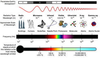
The electromagnetic spectrum is the full range of electromagnetic radiation, organized by frequency or wavelength. The spectrum is divided into separate bands, with different names for the electromagnetic waves within each band. From low to high frequency these are: radio waves, microwaves, infrared, visible light, ultraviolet, X-rays, and gamma rays. The electromagnetic waves in each of these bands have different characteristics, such as how they are produced, how they interact with matter, and their practical applications.

<span class="mw-page-title-main">Infrared</span> Form of electromagnetic radiation

Infrared is electromagnetic radiation (EMR) in the spectral band lower than that of visible light and higher than that of microwaves. In other words, the nominal red edge of the visible spectrum is where infrared transitions to visible light; that is, IR invisible to the human eye. IR is generally understood to encompass wavelengths from around 750 nm to 1000 μm.

<span class="mw-page-title-main">Ultraviolet</span> Energetic, invisible light energy range

Ultraviolet (UV) light is electromagnetic radiation in a range of energies higher than that of visible light, but less than X-rays. UV radiation is present in sunlight, and constitutes about 10% of the total electromagnetic radiation output from the Sun. It is also produced by electric arcs; Cherenkov radiation; and specialized lights, such as mercury-vapor lamps, tanning lamps, and black lights.

Infrared astronomy is a sub-discipline of astronomy which specializes in the observation and analysis of astronomical objects using infrared (IR) radiation. The wavelength of infrared light ranges from 0.75 to 300 micrometers, and falls in between visible radiation, which ranges from 380 to 750 nanometers, and submillimeter waves.

<span class="mw-page-title-main">Forward-looking infrared</span> Type of thermographic camera

Forward-looking infrared (FLIR) cameras, typically used on military and civilian aircraft, use a thermographic camera that senses infrared radiation.

<span class="mw-page-title-main">Thermographic camera</span> Imaging device using infrared radiation

A thermographic camera is a device that creates an image using infrared (IR) radiation, similar to a normal camera that forms an image using visible light. Instead of the 400–700 nanometre (nm) range of the visible light camera, infrared cameras are sensitive to wavelengths from about 1,000 nm to about 14,000 nm (14 μm). The practice of capturing and analyzing the data they provide is called thermography.

<span class="mw-page-title-main">Thermography</span> Infrared imaging used to reveal temperature

Infrared thermography (IRT), thermal video and/or thermal imaging, is a process where a thermal camera captures and creates an image of an object by using infrared radiation emitted from the object in a process, which are examples of infrared imaging science. Thermographic cameras usually detect radiation in the long-infrared range of the electromagnetic spectrum and produce images of that radiation, called thermograms. Since infrared radiation is emitted by all objects with a temperature above absolute zero according to the black body radiation law, thermography makes it possible to see one's environment with or without visible illumination. The amount of radiation emitted by an object increases with temperature; therefore, thermography allows one to see variations in temperature. When viewed through a thermal imaging camera, warm objects stand out well against cooler backgrounds; humans and other warm-blooded animals become easily visible against the environment, day or night. As a result, thermography is particularly useful to the military and other users of surveillance cameras.

<span class="mw-page-title-main">Far infrared</span> Light with 15-1000 μm wavelength

Far infrared (FIR) refers to a specific range within the infrared spectrum of electromagnetic radiation. It encompasses radiation with wavelengths ranging from 15 μm (micrometers) to 1 mm, which corresponds to a frequency range of approximately 20 THz to 300 GHz. This places far infrared radiation within the CIE IR-B and IR-C bands. The longer wavelengths of the FIR spectrum overlap with a range known as terahertz radiation. Different sources may use different boundaries to define the far infrared range. For instance, astronomers often define it as wavelengths between 25 μm and 350 μm. Infrared photons possess significantly lower energy than photons in the visible light spectrum, with tens to hundreds of times less energy.

<span class="mw-page-title-main">Multispectral imaging</span> Capturing image data across multiple electromagnetic spectrum ranges

Multispectral imaging captures image data within specific wavelength ranges across the electromagnetic spectrum. The wavelengths may be separated by filters or detected with the use of instruments that are sensitive to particular wavelengths, including light from frequencies beyond the visible light range, i.e. infrared and ultra-violet. It can allow extraction of additional information the human eye fails to capture with its visible receptors for red, green and blue. It was originally developed for military target identification and reconnaissance. Early space-based imaging platforms incorporated multispectral imaging technology to map details of the Earth related to coastal boundaries, vegetation, and landforms. Multispectral imaging has also found use in document and painting analysis.

<span class="mw-page-title-main">Passive infrared sensor</span> Electronic sensor that measures infrared light

A passive infrared sensor is an electronic sensor that measures infrared (IR) light radiating from objects in its field of view. They are most often used in PIR-based motion detectors. PIR sensors are commonly used in security alarms and automatic lighting applications.

<span class="mw-page-title-main">Motion detector</span> Electrical device which utilizes a sensor to detect nearby motion

A motion detector is an electrical device that utilizes a sensor to detect nearby motion. Such a device is often integrated as a component of a system that automatically performs a task or alerts a user of motion in an area. They form a vital component of security, automated lighting control, home control, energy efficiency, and other useful systems.

<span class="mw-page-title-main">Ultraviolet photography</span> Photographic process using UV radiation

Ultraviolet photography is a photographic process of recording images by using radiation from the ultraviolet (UV) spectrum only. Images taken with ultraviolet radiation serve a number of scientific, medical or artistic purposes. Images may reveal deterioration of art works or structures not apparent under light. Diagnostic medical images may be used to detect certain skin disorders or as evidence of injury. Some animals, particularly insects, use ultraviolet wavelengths for vision; ultraviolet photography can help investigate the markings of plants that attract insects, while invisible to the unaided human eye. Ultraviolet photography of archaeological sites may reveal artifacts or traffic patterns not otherwise visible.

<span class="mw-page-title-main">Electric eye</span>

An electric eye is a photodetector used for detecting obstruction of a light beam. An example is the door safety system used on garage door openers that use a light transmitter and receiver at the bottom of the door to prevent closing if there is any obstruction in the way that breaks the light beam. The device does not provide an image; only the presence of light is detectable. Visible light may be used, but infrared radiation conceals the operation of the device and typically is used in modern systems. Originally, systems used lamps powered by direct current or the power line alternating current frequency, but modern photodetector systems use an infrared light-emitting diode modulated at a few kilohertz, which allows the detector to reject stray light and improves the range, sensitivity, and security of the device.

<span class="mw-page-title-main">Nondispersive infrared sensor</span> Infrared detector without diffracting element dispersing the IR wave lengths

A nondispersive infrared sensor is a simple spectroscopic sensor often used as a gas detector. It is non-dispersive in the fact that no dispersive element is used to separate out the broadband light into a narrow spectrum suitable for gas sensing. The majority of NDIR sensors use a broadband lamp source and an optical filter to select a narrow band spectral region that overlaps with the absorption region of the gas of interest. In this context narrow may be 50-300nm bandwidth. Modern NDIR sensors may use Microelectromechanical systems (MEMs) or mid IR LED sources, with or without an optical filter.

A gas detector is a device that detects the presence of gases in an area, often as part of a safety system. A gas detector can sound an alarm to operators in the area where the leak is occurring, giving them the opportunity to leave. This type of device is important because there are many gases that can be harmful to organic life, such as humans or animals.

Electro-optical MASINT is a subdiscipline of Measurement and Signature Intelligence, (MASINT) and refers to intelligence gathering activities which bring together disparate elements that do not fit within the definitions of Signals Intelligence (SIGINT), Imagery Intelligence (IMINT), or Human Intelligence (HUMINT).

<span class="mw-page-title-main">Missile approach warning system</span> Avionics feature on military aircraft

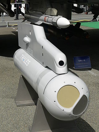
A missile approach warningsystem (MAW) is part of the avionics package on some military aircraft. A sensor detects attacking missiles. Its automatic warning cues the pilot to make a defensive maneuver and deploy the available countermeasures to disrupt missile tracking.

<span class="mw-page-title-main">Quantum well infrared photodetector</span>

A Quantum Well Infrared Photodetector (QWIP) is an infrared photodetector, which uses electronic intersubband transitions in quantum wells to absorb photons. In order to be used for infrared detection, the parameters of the quantum wells in the quantum well infrared photodetector are adjusted so that the energy difference between its first and second quantized states match the incoming infrared photon energy. QWIPs are typically made of gallium arsenide, a material commonly found in smartphones and high-speed communications equipment. Depending on the material and the design of the quantum wells, the energy levels of the QWIP can be tailored to absorb radiation in the infrared region from 3 to 20 µm.

Infrared open-path gas detectors send out a beam of infrared light, detecting gas anywhere along the path of the beam. This linear 'sensor' is typically a few metres up to a few hundred metres in length. Open-path detectors can be contrasted with infrared point sensors.

<span class="mw-page-title-main">Optical beam smoke detector</span>

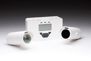
An optical beam smoke detector is a device that uses a projected beam of light to detect smoke across large areas, typically as an indicator of fire. They are used to detect fires in buildings where standard point smoke detectors would either be uneconomical or restricted for use by the height of the building. Optical beam smoke detectors are often installed in warehouses as a cost-effective means of protecting large open spaces.

References

  1. Barrie Jenkins, Peter Mullinger. 2011. Industrial and Process Furnaces: Principles, Design and Operation, Butterworth-Heinemann/IChemE series , p.329. Butterworth-Heinemann. ISBN   0080558062
  2. S. P. Bag. 1995. Fire Services in India: History, Detection, Protection, Management, Environment, Training and Loss Prevention , p. 49. Mittal Publications. ISBN   8170995981
  3. 1 2 Chenebert, A.; Breckon, T.P.; Gaszczak, A. (September 2011). "A non-temporal texture driven approach to real-time fire detection" (PDF). 2011 18th IEEE International Conference on Image Processing. pp. 1781–1784. CiteSeerX   10.1.1.228.875 . doi:10.1109/ICIP.2011.6115796. hdl:1826/7588. ISBN   978-1-4577-1303-3. S2CID   11394788.
  4. Töreyin, B. Ugur; Dedeoglu, Yigithan; Cetin, A. Enis (2005). "Flame detection in video using hidden Markov models". IEEE International Conference on Image Processing 2005 (PDF). Vol. 2. pp. 1230–3. doi:10.1109/ICIP.2005.1530284. hdl:11693/27294. ISBN   978-0-7803-9134-5. S2CID   13205011.
  5. Dunnings, A., Breckon, T.P. (2018). "Experimentally Defined Convolutional Neural Network Architecture Variants for Non-temporal Real-time Fire Detection" (PDF). Proc. International Conference on Image Processing. IEEE. Retrieved 9 August 2018.{{cite book}}: CS1 maint: multiple names: authors list (link)
  6. "Why Flame Rod Failures Happen and How to Prevent Them. | HVAC Service Mentor".
  7. Karner, Don; Francfort, James (December 2003). "Arizona Public Service—Alternative Fuel (Hydrogen) Pilot Plant Design Report" (Document). U.S. Department of Energy FreedomCAR & Vehicle Technologies Program. pp.  Appendix F (pdf).