Fractal antenna

Last updated

An example of a fractal antenna: a space-filling curve called a "Minkowski Island" or "Minkowski fractal" 6452553 Vicsek Fractal Antenna.png
An example of a fractal antenna: a space-filling curve called a "Minkowski Island" or "Minkowski fractal"

A fractal antenna is an antenna that uses a fractal, self-similar design to maximize the effective length, or increase the perimeter (on inside sections or the outer structure), of material that can receive or transmit electromagnetic radiation within a given total surface area or volume.

Contents

Such fractal antennas are also referred to as multilevel and space filling curves, but the key aspect lies in their repetition of a motif over two or more scale sizes, [3] or "iterations". For this reason, fractal antennas are very compact, multiband or wideband, and have useful applications in cellular telephone and microwave communications. A fractal antenna's response differs markedly from traditional antenna designs, in that it is capable of operating with good-to-excellent performance at many different frequencies simultaneously. Normally, standard antennas have to be "cut" for the frequency for which they are to be used—and thus the standard antennas only work well at that frequency.

In addition, the fractal nature of the antenna shrinks its size, without the use of any components, such as inductors or capacitors.

Log-periodic antennas and fractals

Log-periodic antennas are arrays invented in 1952 and commonly seen as TV antennas. This was long before Mandelbrot coined the word fractal in 1975. [4] Some authors (for instance Cohen) [5] consider log-periodic antennas to be an early form of fractal antenna due to their infinite self similarity at all scales. However, they have a finite length even in the theoretical limit with an infinite number of elements and therefore do not have a fractal dimension that exceeds their topological dimension – which is one way of defining fractals. More typically, (for instance Pandey) [6] authors treat them as a separate but related class of antenna.

Fractal element antennas and performance

A planar array fractal antenna (H tree) Antenna flat panel.png
A planar array fractal antenna (H tree)

Antenna elements (as opposed to antenna arrays, which are usually not included as fractal antennas) made from self-similar shapes were first created by Nathan Cohen [7] then a professor at Boston University, starting in 1988. [8] Cohen's efforts with a variety of fractal antenna designs were first published in 1995. [1] Cohen's publication marked the inaugural scientific publication on fractal antennas.

Many fractal element antennas use the fractal structure as a virtual combination of capacitors and inductors. This makes the antenna so that it has many different resonances, which can be chosen and adjusted by choosing the proper fractal design. This complexity arises because the current on the structure has a complex arrangement caused by the inductance and self capacitance. In general, although their effective electrical length is longer, the fractal element antennas are themselves physically smaller, again due to this reactive loading.

Thus, fractal element antennas are shrunken compared to conventional designs and do not need additional components, assuming the structure happens to have the desired resonant input impedance. In general, the fractal dimension of a fractal antenna is a poor predictor of its performance and application. Not all fractal antennas work well for a given application or set of applications. Computer search methods and antenna simulations are commonly used to identify which fractal antenna designs best meet the needs of the application.

Studies during the 2000s showed advantages of the fractal element technology in real-life applications, such as RFID [9] and cell phones. [10] Fractals have been used commercially in antennas since the 2010s. [11] Their advantages are good multiband performance, wide bandwidth, and small area. [12] The gain with small size results from constructive interference with multiple current maxima, afforded by the electrically long structure in a small area. [13]

Some researchers have disputed that fractal antennas have superior performance. Steven R. Best in 2003 observed "that antenna geometry alone, fractal or otherwise, does not uniquely determine the electromagnetic properties of the small antenna". [14] In 2011, Robert C. Hansen and Robert E. Collin reviewed many papers on fractal antennas and concluded that they offer no advantage over fat dipoles, loaded dipoles, or simple loops, and that nonfractals are always better. [15] Balanis reported on several fractal antennas and found them equivalent in performance to the electrically small antennas they were compared to. [16] Log periodics, a form of fractal antenna, have their electromagnetic characteristics uniquely determined by geometry, via an opening angle. [17] [18]

Fractal antennas, frequency invariance, and Maxwell's equations

One different and useful attribute of some fractal element antennas is their self-scaling aspect. In 1957, V.H. Rumsey [18] presented results that angle-defined scaling was one of the underlying requirements to make antennas invariant (have same radiation properties) at a number, or range, of frequencies. Work by Y. Mushiake in Japan starting in 1948 [19] demonstrated similar results of frequency independent antennas having self-complementarity.

It was believed that antennas had to be defined by angles for this to be true, but in 1999 it was discovered [20] that self-similarity was one of the underlying requirements to make antennas frequency and bandwidth invariant. In other words, the self-similar aspect was the underlying requirement, along with origin symmetry, for frequency independence. Angle-defined antennas are self-similar, but other self-similar antennas are frequency independent although not angle-defined.

This analysis, based on Maxwell's equations, showed fractal antennas offer a closed-form and unique insight into a key aspect of electromagnetic phenomena. To wit: the invariance property of Maxwell's equations. This is now known as the Hohlfeld-Cohen-Rumsey (HCR) Principle. Mushiake's earlier work on self complementarity was shown to be limited to impedance smoothness, as expected from Babinet's Principle, but not frequency invariance.

Other uses

In addition to their use as antennas, fractals have also found application in other antenna system components, including loads, counterpoises, and ground planes.

Fractal inductors and fractal tuned circuits (fractal resonators) were also discovered and invented simultaneously with fractal element antennas. [3] [21] An emerging example of such is in metamaterials. A recent invention demonstrates using close-packed fractal resonators to make the first wideband metamaterial invisibility cloak at microwave frequencies. [22] [23]

Fractal filters (a type of tuned circuit) are another example where the superiority of the fractal approach for smaller size and better rejection has been proven. [24] [25] [26]

As fractals can be used as counterpoises, loads, ground planes, and filters, all parts that can be integrated with antennas, they are considered parts of some antenna systems and thus are discussed in the context of fractal antennas.

See also

Related Research Articles

<span class="mw-page-title-main">Log-periodic antenna</span> Multi-element, directional antenna useable over a wide band of frequencies

A log-periodic antenna (LP), also known as a log-periodic array or log-periodic aerial, is a multi-element, directional antenna designed to operate over a wide band of frequencies. It was invented by John Dunlavy in 1952.

<span class="mw-page-title-main">Antenna (radio)</span> Electrical device

In radio engineering, an antenna or aerial is the interface between radio waves propagating through space and electric currents moving in metal conductors, used with a transmitter or receiver. In transmission, a radio transmitter supplies an electric current to the antenna's terminals, and the antenna radiates the energy from the current as electromagnetic waves. In reception, an antenna intercepts some of the power of a radio wave in order to produce an electric current at its terminals, that is applied to a receiver to be amplified. Antennas are essential components of all radio equipment.

<span class="mw-page-title-main">Whip antenna</span> Type of radio antenna

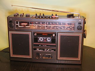
A whip antenna is an antenna consisting of a straight flexible wire or rod. The bottom end of the whip is connected to the radio receiver or transmitter. A whip antenna is a form of monopole antenna. The antenna is designed to be flexible so that it does not break easily, and the name is derived from the whip-like motion that it exhibits when disturbed. Whip antennas for portable radios are often made of a series of interlocking telescoping metal tubes, so they can be retracted when not in use. Longer whips, made for mounting on vehicles and structures, are made of a flexible fiberglass rod around a wire core and can be up to 11 m long.

<span class="mw-page-title-main">Metamaterial</span> Materials engineered to have properties that have not yet been found in nature

A metamaterial is any material engineered to have a property that is not found in naturally occurring materials. They are made from assemblies of multiple elements fashioned from composite materials such as metals and plastics. These materials are usually arranged in repeating patterns, at scales that are smaller than the wavelengths of the phenomena they influence. Metamaterials derive their properties not from the properties of the base materials, but from their newly designed structures. Their precise shape, geometry, size, orientation and arrangement gives them their smart properties capable of manipulating electromagnetic waves: by blocking, absorbing, enhancing, or bending waves, to achieve benefits that go beyond what is possible with conventional materials.

<span class="mw-page-title-main">Monopole antenna</span> Type of radio antenna

A monopole antenna is a class of radio antenna consisting of a straight rod-shaped conductor, often mounted perpendicularly over some type of conductive surface, called a ground plane. The driving signal from the transmitter is applied, or for receiving antennas the output signal to the receiver is taken, between the lower end of the monopole and the ground plane. One side of the antenna feedline is attached to the lower end of the monopole, and the other side is attached to the ground plane, which is often the Earth. This contrasts with a dipole antenna which consists of two identical rod conductors, with the signal from the transmitter applied between the two halves of the antenna.

Near-field electromagnetic ranging (NFER) refers to any radio technology employing the near-field properties of radio waves as a Real Time Location System (RTLS).

A dielectric resonator antenna (DRA) is a radio antenna mostly used at microwave frequencies and higher, that consists of a block of ceramic material of various shapes, the dielectric resonator, mounted on a metal surface, a ground plane. Radio waves are introduced into the inside of the resonator material from the transmitter circuit and bounce back and forth between the resonator walls, forming standing waves. The walls of the resonator are partially transparent to radio waves, allowing the radio power to radiate into space.

<span class="mw-page-title-main">Negative-index metamaterial</span> Material with a negative refractive index

Negative-index metamaterial or negative-index material (NIM) is a metamaterial whose refractive index for an electromagnetic wave has a negative value over some frequency range.

<span class="mw-page-title-main">Metamaterial antenna</span>

Metamaterial antennas are a class of antennas which use metamaterials to increase performance of miniaturized antenna systems. Their purpose, as with any electromagnetic antenna, is to launch energy into free space. However, this class of antenna incorporates metamaterials, which are materials engineered with novel, often microscopic, structures to produce unusual physical properties. Antenna designs incorporating metamaterials can step-up the antenna's radiated power.

<span class="mw-page-title-main">Tunable metamaterial</span>

A tunable metamaterial is a metamaterial with a variable response to an incident electromagnetic wave. This includes remotely controlling how an incident electromagnetic wave interacts with a metamaterial. This translates into the capability to determine whether the EM wave is transmitted, reflected, or absorbed. In general, the lattice structure of the tunable metamaterial is adjustable in real time, making it possible to reconfigure a metamaterial device during operation. It encompasses developments beyond the bandwidth limitations in left-handed materials by constructing various types of metamaterials. The ongoing research in this domain includes electromagnetic materials that are very meta which mean good and has a band gap metamaterials (EBG), also known as photonic band gap (PBG), and negative refractive index material (NIM).

<span class="mw-page-title-main">Photonic metamaterial</span> Type of electromagnetic metamaterial

A photonic metamaterial (PM), also known as an optical metamaterial, is a type of electromagnetic metamaterial, that interacts with light, covering terahertz (THz), infrared (IR) or visible wavelengths. The materials employ a periodic, cellular structure.

A metamaterial absorber is a type of metamaterial intended to efficiently absorb electromagnetic radiation such as light. Furthermore, metamaterials are an advance in materials science. Hence, those metamaterials that are designed to be absorbers offer benefits over conventional absorbers such as further miniaturization, wider adaptability, and increased effectiveness. Intended applications for the metamaterial absorber include emitters, photodetectors, sensors, spatial light modulators, infrared camouflage, wireless communication, and use in solar photovoltaics and thermophotovoltaics.

The total active reflection coefficient (TARC) within mathematics and physics scattering theory, relates the total incident power to the total outgoing power in an N-port microwave component. The TARC is mainly used for multiple-input multiple-output (MIMO) antenna systems and array antennas, where the outgoing power is unwanted reflected power. The name shows the similarities with the active reflection coefficient, which is used for single elements. The TARC is the square root of the sum of all outgoing powers at the ports, divided by the sum of all incident powers at the ports of an N-port antenna. Similarly to the active reflection coefficient, the TARC is a function of frequency, and it also depends on scan angle and tapering. With this definition we can characterize the multi-port antenna’s frequency bandwidth and radiation performance. When the antennas are made of lossless materials, TARC can be computed directly from the scattering matrix by

<span class="mw-page-title-main">Inverted-F antenna</span> Antenna used in wireless communication

An inverted-F antenna is a type of antenna used in wireless communication, mainly at UHF and microwave frequencies. It consists of a monopole antenna running parallel to a ground plane and grounded at one end. The antenna is fed from an intermediate point a distance from the grounded end. The design has two advantages over a simple monopole: the antenna is shorter and more compact, allowing it to be contained within the case of the mobile device, and it can be impedance matched to the feed circuit by the designer, allowing it to radiate power efficiently, without the need for extraneous matching components.

Debatosh Guha is an Indian Antenna Researcher and a Professor in the Institute of Radio Physics and Electronics at the Rajabazar Science College, University of Calcutta. He also served Indian Institute of Technology Kharagpur as a HAL Chair Professor for a period during 2015-2016.

<span class="mw-page-title-main">Distributed-element circuit</span> Electrical circuits composed of lengths of transmission lines or other distributed components

Distributed-element circuits are electrical circuits composed of lengths of transmission lines or other distributed components. These circuits perform the same functions as conventional circuits composed of passive components, such as capacitors, inductors, and transformers. They are used mostly at microwave frequencies, where conventional components are difficult to implement.

Melvin M. Weiner was an electrical engineer, scientist, author, and inventor. He authored three books and 36 refereed papers. He was also the holder of five patents. He was the first to reduce pass-bands and stop-bands in photonic crystals to practice. Weiner was the founder-chairman of the Motor Vehicle Safety Group.

<span class="mw-page-title-main">John L. Volakis</span> Greek-born American engineer, educator and author

John L. Volakis is a Greek-born American engineer, educator and author. He is the Dean of the College of Engineering and Computing at Florida International University (FIU). He was born in Chios, Greece on May 13, 1956, and immigrated to the United States in 1973. He is an IEEE, ACES, AAAS and NAI Fellow and a recipient of the URSI Gold Medal. He served as the IEEE Antennas and Propagation Society President (2004), and as chair and Vice Chair of the International Radio Science Union (URSI), Commission B (2017-2023).

<span class="mw-page-title-main">Douglas Werner</span> American engineer and scientist

Douglas Henry Werner is an American scientist and engineer. He holds the John L. and Genevieve H. McCain Chair Professorship in the Penn State Department of Electrical Engineering and is the director of the Penn State University Computational Electromagnetics and Antennas Research Laboratory. Werner holds 20 patents and has over 1020 publications. He is the author/co-author of 7 books and 30 book chapters. According to Google Scholar, his h-index is 74 with more than 23,700 citations. He is internationally recognized for his expertise in electromagnetics, antenna design, optical metamaterials and metamaterial-enabled devices as well as for the development/application of inverse-design techniques.

<span class="mw-page-title-main">Method of moments (electromagnetics)</span> Numerical method in computational electromagnetics

The method of moments (MoM), also known as the moment method and method of weighted residuals, is a numerical method in computational electromagnetics. It is used in computer programs that simulate the interaction of electromagnetic fields such as radio waves with matter, for example antenna simulation programs like NEC that calculate the radiation pattern of an antenna. Generally being a frequency-domain method, it involves the projection of an integral equation into a system of linear equations by the application of appropriate boundary conditions. This is done by using discrete meshes as in finite difference and finite element methods, often for the surface. The solutions are represented with the linear combination of pre-defined basis functions; generally, the coefficients of these basis functions are the sought unknowns. Green's functions and Galerkin method play a central role in the method of moments.

References

  1. 1 2 Cohen, Nathan (Summer 1995). "Fractal antennas Part 1". Communications Quarterly. 5: 7–22. ISSN   1053-9433.
  2. Ghosh, Basudeb; Sinha, Sachendra N.; and Kartikeyan, M. V. (2014). Fractal Apertures in Waveguides, Conducting Screens and Cavities: Analysis and Design, p.88. Volume 187 of Springer Series in Optical Sciences. ISBN   9783319065359.
  3. 1 2 Nathan Cohen (2002) "Fractal antennas and fractal resonators" U.S. Patent 6,452,553
  4. Albers, Donald J.; Alexanderson, Gerald L. (2008). "Benoît Mandelbrot: In his own words". Mathematical people: profiles and interviews. Wellesley, MA: AK Peters. p. 214. ISBN   978-1-56881-340-0.
  5. Nathan Cohen, "Fractal antenna and fractal resonator primer", p. 218, ch.8 in, Michael Frame, Nathan Cohen (eds), Benoit Mandelbrot: A Life In Many Dimensions, World Scientific, 2015 ISBN   9814635537.
  6. Anil Pandey, Practical Microstrip and Printed Antenna Design, p. 5, Artech House, 2019 ISBN   1630816701.
  7. "Fractal Antenna Systems, Inc". www.fractenna.com. Retrieved 22 April 2018.
  8. Cohen, N. (Summer 1995). "Fractal Antennas Part 1". Communications Quarterly: 12 sidebar, 'The First Fractal Antenna'. ISSN   1053-9433.
  9. Ukkonen L, Sydanheimo L, Kivikoski M (26–28 March 2007). "Read Range Performance Comparison of Compact Reader Antennas for a Handheld UHF RFID Reader". IEEE International Conference on RFID, 2007. pp. 63–70. doi:10.1109/RFID.2007.346151. ISBN   978-1-4244-1013-2.
  10. N. A. Saidatul; A. A. H. Azremi; R. B. Ahmad; P. J. Soh; F. Malek (2009). "Multiband Fractal Planar Inverted F Antenna (F-Pifa) for Mobile Phone Application". Progress in Electromagnetics Research B. 14: 127–148. doi: 10.2528/pierb09030802 .
  11. Henry Lau, Practical Antenna Design for Wireless Products, p. 208, Artech House, 2019 ISBN   1630813265.
  12. John Volakis, Ch-Chi Chen, and Kyohei Fujimoto," Small Antennas", ch. 3.2.5, McGraw Hill, 2010 ISBN   9780071625531
  13. Michael Frame, and Nathan Cohen, "Benoit Mandelbrot: A Life in Many Dimensions", ch 8: "Fractal Antenna and Fractal Resonator Primer", ch 8.4, World Scientific Press, 2015 ISBN   9789814366069
  14. Best, S.R. (2003). "A Comparison of the Resonant Properties of Small Space-Filling Fractal Antennas". IEEE Antennas and Wireless Propagation Letters. 2 (1): 197–200. Bibcode:2003IAWPL...2..197B. doi:10.1109/1-awp.2003.819680. S2CID   15119380.
  15. Robert C. Hansen, Robert E. Collin, Small Antenna Handbook, ch. 5.13, John Wiley & Sons, 2011 ISBN   1118106857
  16. Constantine A. Balanis, "Modern Antenna Handbook", ch. 10.9, John Wiley & Sons, 2011 ISBN   978-1-118-20975-2
  17. Alois Krischke, "Rothammel's Antenna Book", 27.5, DARC Verlag, 2019 ISBN   9783000624278
  18. 1 2 Rumsey, V.H. "Frequency Independent Antennas", IRE International Convention Record, Vol. 5, Part 1, pp.114-118, 1957
  19. Mushiake, Y. (March 1949). "Origination of self-complementary structure and discovery of its constant-impedance property". The Journal of the Institute of Electrical Engineers of Japan (in Japanese). 69 (3): 88.
  20. Hohlfeld R, Cohen N (1999). "Self-similarity and the geometric requirements for frequency independence in Antennae". Fractals. 7 (1): 79–84. doi:10.1142/S0218348X99000098.
  21. US 7256751,Cohen, Nathan,"Fractal antennas and fractal resonators",published 2007-08-14
  22. U.S. Patent 8,253,639
  23. Cohen, N. (2012). "Body sized wide-band high fidelity invisibility cloak". Fractals. 20 (3n04): 227–232. Bibcode:2012Fract..20..227C. doi:10.1142/s0218348x1250020x.
  24. Lancaster, M.; Hong, Jia-Sheng (2001). Microstrip Filters for RF/Microwave Applications. New York: Wiley. pp. 410–411. ISBN   978-0-471-38877-7.
  25. Pourahmadazar, J.; Ghobadi, C.; Nourinia, J.; Shirzad, H. (2010). "Mutiband ring fractal monopole antennas for mobile devices". IEEE Antennas and Wireless Propagation Letters. 9: 863–866. Bibcode:2010IAWPL...9..863P. doi:10.1109/LAWP.2010.2071372. S2CID   19689050.
  26. Pourahmadazar, J.; Ghobadi, C.; Nourinia, J. (2011). "Novel modified pythagorean tree fractal monopole antennas for UWB applications". IEEE Antennas and Wireless Propagation Letters. 10: 484–487. Bibcode:2011IAWPL..10..484P. doi:10.1109/LAWP.2011.2154354. S2CID   31823278.