Log-periodic antenna

Last updated
Log-periodic antenna, 400-4000 MHz LPDA-Antenna.jpg
Log-periodic antenna, 4004000 MHz

A log-periodic antenna (LP), also known as a log-periodic array or log-periodic aerial, is a multi-element, directional antenna designed to operate over a wide band of frequencies. It was invented by John Dunlavy in 1952.

Contents

The most common form of log-periodic antenna is the log-periodic dipole array or LPDA, The LPDA consists of a number of half-wave dipole driven elements of gradually increasing length, each consisting of a pair of metal rods. The dipoles are mounted close together in a line, connected in parallel to the feedline with alternating phase. Electrically, it simulates a series of two or three-element Yagi–Uda antennas connected together, each set tuned to a different frequency.

LPDA antennas look somewhat similar to Yagi antennas, in that they both consist of dipole rod elements mounted in a line along a support boom, but they work in very different ways. Adding elements to a Yagi increases its directionality, or gain, while adding elements to a LPDA increases its frequency response, or bandwidth.

One large application for LPDAs is in rooftop terrestrial television antennas, since they must have large bandwidth to cover the wide television bands of roughly 5488 and 174216 MHz in the VHF and 470890 MHz in the UHF while also having high gain for adequate fringe reception. One widely used design for television reception combined a Yagi for UHF reception in front of a larger LPDA for VHF.

Basic concept

The LPDA normally consists of a series of half wave dipole "elements" each consisting of a pair of metal rods, positioned along a support boom lying along the antenna axis. The elements are spaced at intervals following a logarithmic function of the frequency, known as d or sigma. The length of the successive elements and the spacing between them gradually decrease along the boom. The relationship between the lengths is a function known as tau. Sigma and tau are the key design elements of the LPDA design. [1] [2] The radiation pattern of the antenna is unidirectional, with the main lobe along the axis of the boom, off the end with the shortest elements. Each dipole element is resonant at a wavelength approximately equal to twice its length. The bandwidth of the antenna, the frequency range over which it has maximum gain, is approximately between the resonant frequencies of the longest and shortest element.

Every element in the LPDA antenna is a driven element, that is, connected electrically to the feedline. A parallel wire transmission line usually runs along the central boom, and each successive element is connected in opposite phase to it. The feedline can often be seen zig-zagging across the support boom holding the elements. [2] Another common construction method is to use two parallel central support booms that also acts as the transmission line, mounting the dipoles on the alternate booms. Other forms of the log-periodic design replace the dipoles with the transmission line itself, forming the log-periodic zig-zag antenna. [3] Many other forms using the transmission wire as the active element also exist. [4]

The Yagi and the LPDA designs look very similar at first glance, as they both consist of a number of dipole elements mounted along a support boom. The Yagi, however, has only a single driven element connected to the transmission line, usually the second one from the back of the array, the remaining elements are parasitic. The Yagi antenna differs from the LPDA in having a very narrow bandwidth.

In general terms, at any given frequency the log-periodic design operates somewhat similar to a three-element Yagi antenna; the dipole element closest to resonant at the operating frequency acts as a driven element, with the two adjacent elements on either side as director and reflector to increase the gain, the shorter element in front acting as a director and the longer element behind as a reflector. However, the system is somewhat more complex than that, and all the elements contribute to some degree, so the gain for any given frequency is higher than a Yagi of the same dimensions as any one section of the log-periodic. However, a Yagi with the same number of elements as a log-periodic would have far higher gain, as all of those elements are improving the gain of a single driven element. In its use as a television antenna, it was common to combine a log-periodic design for VHF with a Yagi for UHF, with both halves being roughly equal in size. This resulted in much higher gain for UHF, typically on the order of 10 to 14 dB on the Yagi side and 6.5 dB for the log-periodic. [5] But this extra gain was needed anyway in order to make up for a number of problems with UHF signals.

It should be strictly noted that the log-periodic shape, according to the IEEE definition, [6] [7] does not align with broadband property for antennas. [8] [9] The broadband property of log-periodic antennas comes from its self-similarity. A planar log-periodic antenna can also be made self-complementary, such as logarithmic spiral antennas (which are not classified as log-periodic per se but among the frequency independent antennas that are also self-similar) or the log-periodic toothed design. Y. Mushiake found, for what he termed "the simplest self-complementary planar antenna," a driving point impedance of η0/2=188.4 Ω at frequencies well within its bandwidth limits. [10] [11] [12]

Schwarzbeck UHALP 9108 A.jpg
Log-periodic antenna, 2502400 MHz
VHF UHF LP-antenna closeup.JPG
Log periodic mounted for vertical polarization, covers 140470 MHz
Log periodic VHF TV antenna 1963.jpg
LP television antenna 1963. Covers 5488 MHz and 174218 MHz. Slanted elements were used because on the upper band they operate at the 3rd harmonic.
Log-periodic monopole antenna.png
Wire Log-periodic monopole antenna.

History

The log periodic antenna was invented by John Dunlavy in 1952 while working for the United States Air Force, but was not credited with it due to its "Secret" classification. [13] The University of Illinois at Urbana–Champaign had patented the Isbell and Mayes-Carrel antennas and licensed the design as a package exclusively to JFD Electronics in New York. Channel Master and Blonder Tongue Labs ignored the patents and produced a wide range of antennas based on that design. Lawsuits regarding the antenna patent which the U.I. Foundation lost, evolved into the 1971 Blonder-Tongue Doctrine. This precedent governs patent litigation. [14]

Short wave broadcast antennas

Moosbrunn drehbare logarithmisch-periodische Antenne (2).JPG
Wire log periodic transmitting antenna at international shortwave broadcasting station, Moosbrunn, Austria. Covers 6.123 MHz
LPA antenna suitable for short wave broadcast.png
Diagram of a zig-zag shortwave LPA antenna, black shows metallic conductors, red shows insulating supports

The log periodic is commonly used as a transmitting antenna in high power shortwave broadcasting [15] stations because its broad bandwidth allows a single antenna to transmit on frequencies in multiple bands. The log-periodic zig-zag design with up to 16 sections has been used. These large antennas are typically designed to cover 6 to 26 MHz but even larger ones have been built which operate as low as 2 MHz. Power ratings are available up to 500 kW. Instead of the elements being driven in parallel, attached to a central transmission line, the elements are driven in series, adjacent elements connected at the outer edges. The antenna shown here would have about 14 dBi gain. An antenna array consisting of two such antennas, one above the other and driven in phase has a gain of up to 17 dBi. Being log-periodic, the antenna's main characteristics (radiation pattern, gain, driving point impedance) are almost constant over its entire frequency range, with the match to a 300 Ω feed line achieving a standing wave ratio of better than 2:1 over that range.

Related Research Articles

<span class="mw-page-title-main">Fractal antenna</span> Antenna with a fractal shape

A fractal antenna is an antenna that uses a fractal, self-similar design to maximize the effective length, or increase the perimeter, of material that can receive or transmit electromagnetic radiation within a given total surface area or volume.

<span class="mw-page-title-main">Antenna (radio)</span> Electrical device

In radio engineering, an antenna or aerial is the interface between radio waves propagating through space and electric currents moving in metal conductors, used with a transmitter or receiver. In transmission, a radio transmitter supplies an electric current to the antenna's terminals, and the antenna radiates the energy from the current as electromagnetic waves. In reception, an antenna intercepts some of the power of a radio wave in order to produce an electric current at its terminals, that is applied to a receiver to be amplified. Antennas are essential components of all radio equipment.

<span class="mw-page-title-main">Biconical antenna</span>

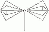
In radio systems, a biconical antenna is a broad-bandwidth antenna made of two roughly conical conductive objects, nearly touching at their points.

<span class="mw-page-title-main">Yagi–Uda antenna</span> Type of radio antenna

A Yagi–Uda antenna, or simply Yagi antenna, is a directional antenna consisting of two or more parallel resonant antenna elements in an end-fire array; these elements are most often metal rods acting as half-wave dipoles. Yagi–Uda antennas consist of a single driven element connected to a radio transmitter and/or receiver through a transmission line, and additional "passive radiators" with no electrical connection, usually including one so-called reflector and any number of directors. It was invented in 1926 by Shintaro Uda of Tohoku Imperial University, Japan, with a lesser role played by his boss Hidetsugu Yagi.

<span class="mw-page-title-main">Directional antenna</span> Radio antenna which has greater performance in specific alignments

A directional antenna or beam antenna is an antenna which radiates or receives greater radio wave power in specific directions. Directional antennas can radiate radio waves in beams, when greater concentration of radiation in a certain direction is desired, or in receiving antennas receive radio waves from one specific direction only. This can increase the power transmitted to receivers in that direction, or reduce interference from unwanted sources. This contrasts with omnidirectional antennas such as dipole antennas which radiate radio waves over a wide angle, or receive from a wide angle.

<span class="mw-page-title-main">Dipole antenna</span> Antenna consisting of two rod shaped conductors

In radio and telecommunications a dipole antenna or doublet is the simplest and most widely used class of antenna. The dipole is any one of a class of antennas producing a radiation pattern approximating that of an elementary electric dipole with a radiating structure supporting a line current so energized that the current has only one node at each end. A dipole antenna commonly consists of two identical conductive elements such as metal wires or rods. The driving current from the transmitter is applied, or for receiving antennas the output signal to the receiver is taken, between the two halves of the antenna. Each side of the feedline to the transmitter or receiver is connected to one of the conductors. This contrasts with a monopole antenna, which consists of a single rod or conductor with one side of the feedline connected to it, and the other side connected to some type of ground. A common example of a dipole is the "rabbit ears" television antenna found on broadcast television sets.

<span class="mw-page-title-main">Whip antenna</span> Type of radio antenna

A whip antenna is an antenna consisting of a straight flexible wire or rod. The bottom end of the whip is connected to the radio receiver or transmitter. A whip antenna is a form of monopole antenna. The antenna is designed to be flexible so that it does not break easily, and the name is derived from the whip-like motion that it exhibits when disturbed. Whip antennas for portable radios are often made of a series of interlocking telescoping metal tubes, so they can be retracted when not in use. Longer whips, made for mounting on vehicles and structures, are made of a flexible fiberglass rod around a wire core and can be up to 11 m long.

<span class="mw-page-title-main">Beverage antenna</span> Type of radio antenna

The Beverage antenna or "wave antenna" is a long-wire receiving antenna mainly used in the low frequency and medium frequency radio bands, invented by Harold H. Beverage in 1921. It is used by amateur radio, shortwave listening, and longwave radio DXers and military applications.

<span class="mw-page-title-main">J-pole antenna</span>

The J-pole antenna, more properly known as the J antenna, is a vertical omnidirectional transmitting antenna used in the shortwave frequency bands. It was invented by Hans Beggerow in 1909 for use in Zeppelin airships. Trailed behind the airship, it consisted of a single one half wavelength long wire radiator, in series with a quarter-wave parallel transmission line tuning stub which matches the antenna impedance to the feedline. By 1936 this antenna began to be used for land-based transmitters with the radiating element and the matching section mounted vertically, giving it the shape of the letter "J", and was named the J antenna by 1943. When the radiating half-wave section is mounted horizontally, at right-angles to the quarter-wave matching stub, the variation is usually called a Zepp antenna.

<span class="mw-page-title-main">Television antenna</span> Antenna used with a television to receive television programs

A television antenna is an antenna specifically designed for use with a television receiver (TV) to receive over-the-air broadcast television signals from a television station. Television reception is dependent upon the antenna as well as the transmitter. Terrestrial television is broadcast on frequencies from about 47 to 250 MHz in the very high frequency (VHF) band, and 470 to 960 MHz in the ultra high frequency (UHF) band in different countries. Television antennas are manufactured in two different types: "indoor" antennas, to be located on top of or next to the television set, and "outdoor" antennas, mounted on a mast on top of the owner's house. They can also be mounted in a loft or attic, where the dry conditions and increased elevation are advantageous for reception and antenna longevity. Outdoor antennas are more expensive and difficult to install, but are necessary for adequate reception in fringe areas far from television stations. The most common types of indoor antennas are the dipole and loop antennas, and for outdoor antennas the Yagi, log periodic, and for UHF channels the multi-bay reflective array antenna.

<span class="mw-page-title-main">Monopole antenna</span> Type of radio antenna

A monopole antenna is a class of radio antenna consisting of a straight rod-shaped conductor, often mounted perpendicularly over some type of conductive surface, called a ground plane. The driving signal from the transmitter is applied, or for receiving antennas the output signal to the receiver is taken, between the lower end of the monopole and the ground plane. One side of the antenna feedline is attached to the lower end of the monopole, and the other side is attached to the ground plane, which is often the Earth. This contrasts with a dipole antenna which consists of two identical rod conductors, with the signal from the transmitter applied between the two halves of the antenna.

A radio transmitter or receiver is connected to an antenna which emits or receives the radio waves. The antenna feed system or antenna feed is the cable or conductor, and other associated equipment, which connects the transmitter or receiver with the antenna and makes the two devices compatible. In a radio transmitter, the transmitter generates an alternating current of radio frequency, and the feed system feeds the current to the antenna, which converts the power in the current to radio waves. In a radio receiver, the incoming radio waves excite tiny alternating currents in the antenna, and the feed system delivers this current to the receiver, which processes the signal.

<span class="mw-page-title-main">Corner reflector antenna</span>

A corner reflector antenna is a type of directional antenna used at VHF and UHF frequencies. It was invented by John D. Kraus in 1938. It consists of a dipole driven element mounted in front of two flat rectangular reflecting screens joined at an angle, usually 90°. Corner reflector antennas have moderate gain of 10–15 dB, high front-to-back ratio of 20–30 dB, and wide bandwidth.

<span class="mw-page-title-main">Quad antenna</span> Type of radio antenna

A quad antenna is a type of directional wire radio antenna used on the HF and VHF bands. Like a Yagi–Uda antenna ("Yagi"), a quad consists of a driven element and one or more parasitic elements; however in a quad, each of these elements is a loop antenna, which may be square, round, or some other shape. It is used by radio amateurs on the HF and VHF amateur bands.

<span class="mw-page-title-main">Turnstile antenna</span>

A turnstile antenna, or crossed-dipole antenna, is a radio antenna consisting of a set of two identical dipole antennas mounted at right angles to each other and fed in phase quadrature; the two currents applied to the dipoles are 90° out of phase. The name reflects the notion the antenna looks like a turnstile when mounted horizontally. The antenna can be used in two possible modes. In normal mode the antenna radiates horizontally polarized radio waves perpendicular to its axis. In axial mode the antenna radiates circularly polarized radiation along its axis.

A shortwave broadband antenna is a radio antenna that can be used for transmission of any shortwave radio band from among the greater part of the shortwave radio spectrum, without requiring any band-by-band adjustment of the antenna. Generally speaking, there is no difficulty in building an adequate receiving antenna; the challenge is designing an antenna which can be used for transmission without an adjustable impedance matching network.

<span class="mw-page-title-main">Antenna array</span>

An antenna array is a set of multiple connected antennas which work together as a single antenna, to transmit or receive radio waves. The individual antennas are usually connected to a single receiver or transmitter by feedlines that feed the power to the elements in a specific phase relationship. The radio waves radiated by each individual antenna combine and superpose, adding together to enhance the power radiated in desired directions, and cancelling to reduce the power radiated in other directions. Similarly, when used for receiving, the separate radio frequency currents from the individual antennas combine in the receiver with the correct phase relationship to enhance signals received from the desired directions and cancel signals from undesired directions. More sophisticated array antennas may have multiple transmitter or receiver modules, each connected to a separate antenna element or group of elements.

<span class="mw-page-title-main">Self-complementary antenna</span> Type of antenna

The self-complementary antenna (SCA) is a basic antenna for extremely broadband practical antennas. This antenna is an arbitrarily shaped antenna which is constituted with a half of an infinitely extended planar-sheet conductor such that the shape of its complementary structure is exactly identical, or "self-complementary" with that of the original structure with two terminals for the simplest case. The self-complementary antenna has constant input impedance independent of the source frequency and the shape of the structure.

In radio systems, many different antenna types are used whose properties are especially crafted for particular applications. Antennas can be classified in various ways. The list below groups together antennas under common operating principles, following the way antennas are classified in many engineering textbooks.

In an antenna array made of multiple conductive elements, a driven element or active element is electrically connected to the receiver or transmitter while a parasitic element or passive radiator is not.

References

  1. The Log-Periodic Dipole Array"
  2. 1 2 "Log Periodic Dipole Array (LPDA)". www.ewh.ieee.org.
  3. "Log-periodic zig zag antenna", US Patent 3355740
  4. Photo Archive Of Antennas, Illinois Historic Archive
  5. Davidson, David (2010). Computational Electromagnetics for RF and Microwave Engineering. Cambridge University Press. p. 178. ISBN   978-1-139-49281-2.
  6. "Log-periodic antenna Any one of a class of antennas having a structural geometry such that its impedance and radiation characteristics repeat periodically as the logarithm of frequency." (see The new IEEE Standard Dictionary of Electrical and Electronics Terms, 1993 ⓒ IEEE.)
  7. "Log-periodic antenna Any one of a class of antennas having a structural geometry such that its impedance and radiation characteristics repeat periodically as the logarithm of frequency." (see Acknowledgments, and footnote in page 1), Self-Complementary Antennas―Principle of Self-Complementarity for Constant Impedance―, by Mushiake, Yasuto, Springer-Verlag London Ltd., London, 1996.
  8. Mushiake, Yasuto, "Constant-impedance antennas", J. IECE Japan, 48, 4, pp. 580-584, April 1965. (in Japanese).
  9. Mushiake, Yasuto (March 1949). "Log-periodic structure provides no broad-band property for antennas". J. IEE Japan. Sm.rim.or.jp. 69 (3): 88. Retrieved 15 January 2014.
  10. Mushiake, Yasuto (March 1949). "Origination of self-complementary structure and discovery of its constant-impedance property". J. IEE Japan (in Japanese). Sm.rim.or.jp. 69 (3): 88. Retrieved 31 January 2014.
  11. Mushiake, Yasuto. "Infinite freedom". Sm.rim.or.jp. Retrieved 15 January 2014.
  12. Rumsey, V. H., Frequency independent antennas, Academic Press, New York and London. 1966. [p. 55]
  13. John Atkinson (24 August 1996). "Loudspeaker designer John Dunlavy: By the Numbers". Stereophile. page 4.
  14. "Blonder–Tongue Doctrine Law and Legal Definition". definitions.uslegal.com. USLegal, Inc. Archived from the original on Mar 25, 2023. Retrieved 2022-05-04.
  15. "Antennas for the Shortwave Broadcaster". www.antenna.be.

Bibliography

Notes

PD-icon.svg This article incorporates public domain material from Federal Standard 1037C. General Services Administration. (in support of MIL-STD-188).

See also