Free-piston engine

Last updated
Free-piston engine used as a gas generator to drive a turbine Pescara avec turbine.gif
Free-piston engine used as a gas generator to drive a turbine

A free-piston engine is a linear, 'crankless' internal combustion engine, in which the piston motion is not controlled by a crankshaft but determined by the interaction of forces from the combustion chamber gases, a rebound device (e.g., a piston in a closed cylinder) and a load device (e.g. a gas compressor or a linear alternator).

Contents

The purpose of all such piston engines is to generate power. In the free-piston engine, this power is not delivered to a crankshaft but is instead extracted through either exhaust gas pressure driving a turbine, through driving a linear load such as an air compressor for pneumatic power, or by incorporating a linear alternator directly into the pistons to produce electrical power.

The basic configuration of free-piston engines is commonly known as single piston, dual piston or opposed pistons, referring to the number of combustion cylinders. The free-piston engine is usually restricted to the two-stroke operating principle, since a power stroke is required every fore-and-aft cycle. However, a split cycle four-stroke version has been patented, GB2480461 (A) published 2011-11-23. [1]

First generation

Figure 1 of US1657641 US1657641-figure-1.png
Figure 1 of US1657641

The modern free-piston engine was proposed by R.P. Pescara [2] and the original application was a single piston air compressor. Pescara set up the Bureau Technique Pescara to develop free-piston engines and Robert Huber was technical director of the Bureau from 1924 to 1962. [3]

The engine concept was a topic of much interest in the period 1930–1960, and a number of commercially available units were developed. These first generation free-piston engines were without exception opposed piston engines, in which the two pistons were mechanically linked to ensure symmetric motion. The free-piston engines provided some advantages over conventional technology, including compactness and a vibration-free design.

Air compressors

The first successful application of the free-piston engine concept was as air compressors. In these engines, air compressor cylinders were coupled to the moving pistons, often in a multi-stage configuration. Some of these engines utilised the air remaining in the compressor cylinders to return the piston, thereby eliminating the need for a rebound device.

Free-piston air compressors were in use among others by the German Navy, and had the advantages of high efficiency, compactness and low noise and vibration. [4]

Gas generators

After the success of the free-piston air compressor, a number of industrial research groups started the development of free-piston gas generators. In these engines there is no load device coupled to the engine itself, but the power is extracted from an exhaust turbine. The turbine's rotary motion can thus drive a pump, propeller, generator, or other device.

In this arrangement, the only load for the engine is supercharging the inlet air, albeit in theory some of this air could be diverted for use as a compressed-air source if desired. Such a modification would enable the free-piston engine, when used in conjunction with the aforementioned exhaust-driven turbine, to provide both motive power (from the output shaft of the turbine) in addition to compressed air on demand.

A number of free-piston gas generators were developed, and such units were in widespread use in large-scale applications such as stationary and marine powerplants. [5] Attempts were made to use free-piston gas generators for vehicle propulsion (e.g. in gas turbine locomotives) but without success. [6] [7]

Modern applications

Modern applications of the free-piston engine concept include hydraulic engines, aimed for off-highway vehicles, and free-piston engine generators, aimed for use with hybrid electric vehicles.

Hydraulic

These engines are commonly of the single piston type, with the hydraulic cylinder acting as both load and rebound device using a hydraulic control system. This gives the unit high operational flexibility. Excellent part load performance has been reported. [8] [9]

Generators

Free-piston linear generators that eliminate a heavy crankshaft with electrical coils in the piston and cylinder walls are being investigated by multiple research groups for use in hybrid electric vehicles as range extenders. The first free piston generator was patented in 1934. [10] Examples include the Stelzer engine and the Free Piston Power Pack manufactured by Pempek Systems based on a German patent. [11] A single piston Free-piston linear generator was demonstrated in 2013 at the German Aerospace Center (Deutsches Zentrum für Luft- und Raumfahrt; DLR). [12]

These engines are mainly of the dual piston type, giving a compact unit with high power-to-weight ratio. A challenge with this design is to find an electric motor with sufficiently low weight. Control challenges in the form of high cycle-to-cycle variations were reported for dual piston engines. [13] [14]

In June 2014 Toyota announced a prototype Free Piston Engine Linear Generator (FPEG). As the piston is forced downward during its power stroke it passes through windings in the cylinder to generate a burst of three-phase AC electricity. The piston generates electricity on both strokes, reducing piston dead losses. The generator operates on a two-stroke cycle, using hydraulically activated exhaust poppet valves, gasoline direct injection and electronically operated valves. The engine is easily modified to operate under various fuels including hydrogen, natural gas, ethanol, gasoline and diesel. A two-cylinder FPEG is inherently balanced. [15]

Toyota claims a thermal-efficiency rating of 42% in continuous use, greatly exceeding today's average of 25-30%. Toyota demonstrated a 24 inch long by 2.5 inch in diameter unit producing 15 hp (greater than 11 kW). [16]

Features

The operational characteristics of free-piston engines differ from those of conventional, crankshaft engines. The main difference is due to the piston motion not being restricted by a crankshaft in the free-piston engine, leading to the potentially valuable feature of variable compression ratio. This does, however, also present a control challenge, since the position of the dead centres must be accurately controlled in order to ensure fuel ignition and efficient combustion, and to avoid excessive in-cylinder pressures or, worse, the piston hitting the cylinder head. The free-piston engine has a number of unique features, some give it potential advantages and some represent challenges that must be overcome for the free-piston engine to be a realistic alternative to conventional technology.

As the piston motion between the endpoints is not mechanically restricted by a crank mechanism, the free-piston engine has the valuable feature of variable compression ratio, which may provide extensive operation optimization, higher part load efficiency and possible multi-fuel operation. These are enhanced by variable fuel injection timing and valve timing through proper control methods.

Variable stroke length is achieved by a proper frequency control scheme such as PPM (Pulse Pause Modulation) control [1], in which piston motion is paused at BDC using a controllable hydraulic cylinder as rebound device. The frequency can therefore be controlled by applying a pause between the time the piston reaches BDC and the release of compression energy for the next stroke.

Since there are fewer moving parts, the frictional losses and manufacturing cost are reduced. The simple and compact design thus requires less maintenance and this increases lifetime.

The purely linear motion leads to very low side loads on the piston, hence lesser lubrication requirements for the piston.

The combustion process of free piston engine is well suited for Homogeneous Charge Compression Ignition (HCCI) mode, in which the premixed charge is compressed and self-ignited, resulting in very rapid combustion, along with lower requirements for accurate ignition timing control. Also, high efficiencies are obtained due to nearly constant volume combustion and the possibility to burn lean mixtures to reduce gas temperatures and thereby some types of emissions.

By running multiple engines in parallel, vibrations due to balancing issues may be reduced, but this requires accurate control of engine speed. Another possibility is to apply counterweights, which results in more complex design, increased engine size and weight and additional friction losses.

Lacking a kinetic energy storage device, like a flywheel in conventional engines, free-piston engines are more susceptible to shutdown caused by minute variations in the timing or pressure of the engine cycle. Precise control of the speed and timing is required as, if the engine fails to build up sufficient compression or if other factors influence the injection/ignition and combustion, the engine may misfire or stop.

Advantages

Potential advantages of the free-piston concept include:

Challenges

The main challenge for the free-piston engine is engine control, which can only be said to be fully solved for single piston hydraulic free-piston engines. Issues such as the influence of cycle-to-cycle variations in the combustion process and engine performance during transient operation in dual piston engines are topics that need further investigation. Crankshaft engines can connect traditional accessories such as alternator, oil pump, fuel pump, cooling system, starter etc.

Rotational movement to spin conventional automobile engine accessories such as alternators, air conditioner compressors, power steering pumps, and anti-pollution devices could be captured from a turbine situated in the exhaust stream.

Opposing piston engine

Most free piston engines are of the opposed piston type with a single central combustion chamber. A variation is the Opposing piston engine which has two separate combustion chambers. An example is the Stelzer engine.

Recent developments

In the 21st century, research continues into free-piston engines and patents have been published in many countries. In the UK, Newcastle University is undertaking research into free-piston engines. [20]

A new kind of the free-piston engine, a Free-piston linear generator is being developed by the German aerospace center. [21]

In addition to these prototypes, researchers at West Virginia University in the US, are working on the development of a single cylinder free-piston engine prototype with mechanical springs at an operating frequency of 90 Hz. [22]

Related Research Articles

<span class="mw-page-title-main">Engine</span> Machine that converts one or more forms of energy into mechanical energy (of motion)

An engine or motor is a machine designed to convert one or more forms of energy into mechanical energy.

<span class="mw-page-title-main">Reciprocating engine</span> Engine utilising one or more reciprocating pistons

A reciprocating engine, also often known as a piston engine, is typically a heat engine that uses one or more reciprocating pistons to convert high temperature and high pressure into a rotating motion. This article describes the common features of all types. The main types are: the internal combustion engine, used extensively in motor vehicles; the steam engine, the mainstay of the Industrial Revolution; and the Stirling engine for niche applications. Internal combustion engines are further classified in two ways: either a spark-ignition (SI) engine, where the spark plug initiates the combustion; or a compression-ignition (CI) engine, where the air within the cylinder is compressed, thus heating it, so that the heated air ignites fuel that is injected then or earlier.

<span class="mw-page-title-main">Miller cycle</span> Thermodynamic cycle

In engineering, the Miller cycle is a thermodynamic cycle used in a type of internal combustion engine. The Miller cycle was patented by Ralph Miller, an American engineer, U.S. patent 2,817,322 dated Dec 24, 1957. The engine may be two- or four-stroke and may be run on diesel fuel, gases, or dual fuel. It uses a supercharger or a turbocharger to offset the performance loss of the Atkinson cycle.

<span class="mw-page-title-main">Two-stroke engine</span> Internal combustion engine type

A two-strokeengine is a type of internal combustion engine that completes a power cycle with two strokes of the piston in one revolution of the crankshaft. A four-stroke engine requires four strokes of the piston to complete a power cycle in two crankshaft revolutions. In a two-stroke engine, the end of the combustion stroke and the beginning of the compression stroke happen simultaneously, with the intake and exhaust functions occurring at the same time.

<span class="mw-page-title-main">Starter (engine)</span> Device used to start an internal combustion engine

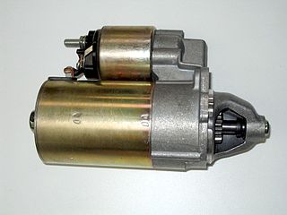
A starter is a device used to rotate (crank) an internal-combustion engine so as to initiate the engine's operation under its own power. Starters can be electric, pneumatic, or hydraulic. The starter can also be another internal-combustion engine in the case, for instance, of very large engines, or diesel engines in agricultural or excavation applications.

<span class="mw-page-title-main">Four-stroke engine</span> Internal combustion engine type

A four-strokeengine is an internal combustion (IC) engine in which the piston completes four separate strokes while turning the crankshaft. A stroke refers to the full travel of the piston along the cylinder, in either direction. The four separate strokes are termed:

  1. Intake: Also known as induction or suction. This stroke of the piston begins at top dead center (T.D.C.) and ends at bottom dead center (B.D.C.). In this stroke the intake valve must be in the open position while the piston pulls an air-fuel mixture into the cylinder by producing a partial vacuum in the cylinder through its downward motion.
  2. Compression: This stroke begins at B.D.C, or just at the end of the suction stroke, and ends at T.D.C. In this stroke the piston compresses the air-fuel mixture in preparation for ignition during the power stroke (below). Both the intake and exhaust valves are closed during this stage.
  3. Combustion: Also known as power or ignition. This is the start of the second revolution of the four stroke cycle. At this point the crankshaft has completed a full 360 degree revolution. While the piston is at T.D.C. the compressed air-fuel mixture is ignited by a spark plug or by heat generated by high compression, forcefully returning the piston to B.D.C. This stroke produces mechanical work from the engine to turn the crankshaft.
  4. Exhaust: Also known as outlet. During the exhaust stroke, the piston, once again, returns from B.D.C. to T.D.C. while the exhaust valve is open. This action expels the spent air-fuel mixture through the exhaust port.

In spark-ignition internal combustion engines, knocking occurs when combustion of some of the air/fuel mixture in the cylinder does not result from propagation of the flame front ignited by the spark plug, but when one or more pockets of air/fuel mixture explode outside the envelope of the normal combustion front. The fuel–air charge is meant to be ignited by the spark plug only, and at a precise point in the piston's stroke. Knock occurs when the peak of the combustion process no longer occurs at the optimum moment for the four-stroke cycle. The shock wave creates the characteristic metallic "pinging" sound, and cylinder pressure increases dramatically. Effects of engine knocking range from inconsequential to completely destructive.

<span class="mw-page-title-main">Opposed-piston engine</span> Combustion engine using disks compressing fuel in the same cylinder

An opposed-piston engine is a piston engine in which each cylinder has a piston at both ends, and no cylinder head. Petrol and diesel opposed-piston engines have been used mostly in large-scale applications such as ships, military tanks, and factories. Current manufacturers of opposed-piston engines include Cummins, Achates Power and Fairbanks-Morse Defense (FMDefense).

<span class="mw-page-title-main">Brayton cycle</span> Thermodynamic cycle

The Brayton cycle, also known as the Joule cycle, is a thermodynamic cycle that describes the operation of certain heat engines that have air or some other gas as their working fluid. It is characterized by isentropic compression and expansion, and isobaric heat addition and rejection, though practical engines have adiabatic rather than isentropic steps.

<span class="mw-page-title-main">Atkinson cycle</span> Thermodynamic cycle

The Atkinson-cycle engine is a type of internal combustion engine invented by James Atkinson in 1882. The Atkinson cycle is designed to provide efficiency at the expense of power density.

Variable compression ratio (VCR) is a technology to adjust the compression ratio of an internal combustion engine while the engine is in operation. This is done to increase fuel efficiency while under varying loads. Variable compression engines allow the volume above the piston at top dead centre to be changed. Higher loads require lower ratios to increase power, while lower loads need higher ratios to increase efficiency, i.e. to lower fuel consumption. For automotive use this needs to be done as the engine is running in response to the load and driving demands. The 2019 Infiniti QX50 is the first commercially available vehicle that uses a variable compression ratio engine.

A swing-piston engine is a type of internal combustion engine in which the pistons move in a circular motion inside a ring-shaped "cylinder", moving closer and further from each other to provide compression and expansion. Generally two sets of pistons are used, geared to move in a fixed relationship as they rotate around the cylinder. In some versions the pistons oscillate around a fixed center, as opposed to rotating around the entire engine. The design has also been referred to as a oscillating piston engine, vibratory engine when the pistons oscillate instead of rotate, or toroidal engine based on the shape of the "cylinder".

<span class="mw-page-title-main">Timeline of heat engine technology</span>

This timeline of heat engine technology describes how heat engines have been known since antiquity but have been made into increasingly useful devices since the 17th century as a better understanding of the processes involved was gained. A heat engine is any system that converts heat to mechanical energy, which can then be used to do mechanical work.They continue to be developed today.

<span class="mw-page-title-main">Hot-bulb engine</span> Internal combustion engine

The hot-bulb engine, also known as a semi-diesel, is a type of internal combustion engine in which fuel ignites by coming in contact with a red-hot metal surface inside a bulb, followed by the introduction of air (oxygen) compressed into the hot-bulb chamber by the rising piston. There is some ignition when the fuel is introduced, but it quickly uses up the available oxygen in the bulb. Vigorous ignition takes place only when sufficient oxygen is supplied to the hot-bulb chamber on the compression stroke of the engine.

<span class="mw-page-title-main">Two-stroke diesel engine</span> Engine type

A two-stroke diesel engine is a diesel engine that uses compression ignition in a two-stroke combustion cycle. It was invented by Hugo Güldner in 1899.

Two- and four-stroke engines are engines that combine elements from both two-stroke and four-stroke engines. They usually incorporate two pistons.

Internal combustion engines come in a wide variety of types, but have certain family resemblances, and thus share many common types of components.

<span class="mw-page-title-main">Aircraft engine starting</span> Overview article on aircraft engine starting methods

Many variations of aircraft engine starting have been used since the Wright brothers made their first powered flight in 1903. The methods used have been designed for weight saving, simplicity of operation and reliability. Early piston engines were started by hand. Geared hand starting, electrical and cartridge-operated systems for larger engines were developed between the First and Second World Wars.

<span class="mw-page-title-main">Internal combustion engine</span> Engine in which the combustion of a fuel occurs with an oxidizer in a combustion chamber

An internal combustion engine is a heat engine in which the combustion of a fuel occurs with an oxidizer in a combustion chamber that is an integral part of the working fluid flow circuit. In an internal combustion engine, the expansion of the high-temperature and high-pressure gases produced by combustion applies direct force to some component of the engine. The force is typically applied to pistons, turbine blades, a rotor, or a nozzle. This force moves the component over a distance, transforming chemical energy into kinetic energy which is used to propel, move or power whatever the engine is attached to.

The free-piston linear generator (FPLG) uses chemical energy from fuel to drive magnets through a stator and converts this linear motion into electric energy. Because of its versatility, low weight and high efficiency, it can be used in a wide range of applications, although it is of special interest to the mobility industry as range extenders for electric vehicles.

References

  1. "Espacenet - Original document".
  2. Pescara R.P., Motor compressor apparatus, US Patent 1,657,641, 1928.
  3. "History". freikolben.ch. Archived from the original on 2012-04-22. Retrieved 2015-03-27.
  4. Toutant, W.T. (1952). "The Worthington–Junkers free-piston air compressor". Journal of the American Society of Naval Engineers (64): 583–594.
  5. London A.L., Oppenheim A.K., The free-piston engine development -- Present status and design aspects, Transactions of the ASME 1952:74:1349–1361.
  6. Underwood A.F., The GMR 4-4 ‘‘HYPREX’’ engine – A concept of the free-piston engine for automotive use, SAE Transactions 1957:65:377–391.
  7. Frey D.N. et al., The automotive free-piston-turbine engine, SAE Transactions 1957:65:628–634.
  8. Achten P.A.J. et al., Horsepower with brains: The design of the Chiron free piston engine, SAE Paper 2000–01–2545, 2000.
  9. Brunner H. et al., Renaissance einer Kolbenmachine, Antriebstechnik 2005:4:66–70.
  10. P. OSTENBERG. Electric generator. US Patent 2362151 A - 1959.
  11. Willimczik W. Hubkolbenmaschine mit elektrischem Triebwerk, insbesondere Hubkolben-Lineargenerator, WP113 593, 1974
  12. Prof. Dr.-Ing. Horst E. Friedrich, German Aerospace Center (DLR), , 19 February 2013
  13. Clark N. et al., Modelling and development of a linear engine, Proc. ASME Spring Conference, Internal Combustion Engine Division, 1998:30:49–57.
  14. Tikkanen S. et al., First cycles of the dual hydraulic free piston engine, SAE Paper 2000–01–2546, 2000.
  15. BioAge Media. "Toyota Central R& developing free-piston engine linear generator; envisioning multi-FPEG units for electric drive vehicles". greencarcongress.com.
  16. Cammisa, Jason (June 30, 2014). "No crankshaft, no problem: Toyota's free piston engine is brilliant". Road and Track.
  17. Van Blarigan P. Advanced internal combustion electric generator
  18. Mikalsen R, Roskilly A.P. The design and simulation of a two-stroke free-piston compression ignition engine for electrical power generation. Applied Thermal Engineering, Volume 28, Issues 5-6, Pages 589-600, 2008.
  19. Mikalsen R, Roskilly A.P. A computational study of free-piston diesel engine combustion. Applied Energy, Volume 86, Issues 7-8, Pages 1136-1143, 2009.
  20. "Home". free-piston.eu.
  21. DLR researchers unveil a new kind of range extender for electric cars
  22. Bade, Mehar, Nigel N. Clark, Matthew C. Robinson, and Parviz Famouri. "Parametric Investigation of Combustion and Heat Transfer Characteristics of Oscillating Linear Engine Alternator." Journal of Combustion 2018 (2018).

Sources