Transmission of motion and force by gear wheels, compound train.[1]
Illustration by Georgius Agricola (1580) showing a toothed wheel that engages a slotted cylinder to form a gear train that transmits power from a human-powered treadmill to mining pump.
A gear train or gear set is a machine element of a mechanical system formed by mounting two or more gears on a frame such that the teeth of the gears engage.
Gear teeth are designed to ensure the pitch circles of engaging gears roll on each other without slipping, providing a smooth transmission of rotation from one gear to the next.[2] Features of gears and gear trains include:
The gear ratio of the pitch circles of mating gears defines the speed ratio and the mechanical advantage of the gear set.
The transmission of rotation between contacting toothed wheels can be traced back to the Antikythera mechanism of Greece and the south-pointing chariot of China. Illustrations by the Renaissance scientist Georgius Agricola show gear trains with cylindrical teeth. The implementation of the involute tooth yielded a standard gear design that provides a constant speed ratio.
Gear ratio
Two meshed spur gears showing tangent contact between their pitch circles, each illustrated with broken blue lines; the gear on the left has 10 teeth and the gear on the right has 15 teeth.
Dimensions and terms
The pitch circle of a given gear is determined by the tangent point contact between two meshing gears; for example, two spur gears mesh together when their pitch circles are tangent, as illustrated.[3]:529
The pitch diameter is the diameter of a gear's pitch circle, measured through that gear's rotational centerline, and the pitch radius is the radius of the pitch circle.[3]:529 The distance between the rotational centerlines of two meshing gears is equal to the sum of their respective pitch radii.[3]:533
The circular pitch is the distance, measured along the pitch circle, between one tooth and the corresponding point on an adjacent tooth.[3]:529
The number of teeth per gear is an integer determined by the pitch circle and circular pitch.
Relationships
Spur gear tooth dimensions and how they are measured:
t = tooth thickness, along the pitch circle
p = circular pitch, along the pitch circle
a = addendum, radially
b = dedendum, radially
In this example, the gear has 20 teeth.
The circular pitch of a gear can be defined as the circumference of the pitch circle using its pitch radius divided by the number of teeth :[3]:530
The thickness of each tooth, measured through the pitch circle, is equal to the gap between neighboring teeth (also measured through the pitch circle) to ensure the teeth on adjacent gears, cut to the same tooth profile, can mesh without interference. This means the circular pitch is equal to twice the thickness of a tooth,[3]:535
In the United States, the diametral pitch is the number of teeth on a gear divided by the pitch diameter; for SI countries, the module is the reciprocal of this value.[3]:529 For any gear, the relationship between the number of teeth, diametral pitch or module, and pitch diameter is given by:
Since the pitch diameter is related to circular pitch as
this means
Rearranging, we obtain a relationship between diametral pitch and circular pitch:[3]:530
Gear or speed ratio
Two meshing gears transmit rotational motion; note difference in rotational speeds is equal to the reciprocal of the ratio between the number of teeth on the two gears
For a pair of meshing gears, the angular speed ratio, also known as the gear ratio, can be computed from the ratio of the pitch radii or the ratio of the number of teeth on each gear. Define the angular speed ratio of two meshed gears A and B as the ratio of the magnitude of their respective angular velocities:
Here, subscripts are used to designate the gear, so gear A has a radius of and angular velocity of with teeth, which meshes with gear B which has corresponding values for radius , angular velocity , and teeth.
When these two gears are meshed and turn without slipping, the velocity of the tangent point where the two pitch circles come in contact is the same on both gears, and is given by:[3]:533
Rearranging, the ratio of angular velocity magnitudes is the inverse of the ratio of pitch circle radii:
Therefore, the angular speed ratio can be determined from the respective pitch radii:[3]:533,552
For example, if gear A has a pitch circle radius of 1in (25mm) and gear B has a pitch circle radius of 2in (51mm), the angular speed ratio is 2, which is sometimes written as 2:1. Gear A turns at twice the speed of gear B. For every complete revolution of gear A (360°), gear B makes half a revolution (180°).
In addition, consider that in order to mesh smoothly and turn without slipping, these two gears A and B must have compatible teeth. Given the same tooth and gap widths, they also must have the same circular pitch , which means
or, equivalently
This equation can be rearranged to show the ratio of the pitch circle radii of two meshing gears is equal to the ratio of their number of teeth:
Since the angular speed ratio depends on the ratio of pitch circle radii, it is equivalently determined by the ratio of the number of teeth:
In other words, the [angular] speed ratio is inversely proportional to the radius of the pitch circle and the number of teeth of gear A, and directly proportional to the same values for gear B.
Torque ratio analysis using virtual work
The gear ratio also determines the transmitted torque. The torque ratio of the gear train is defined as the ratio of its output torque to its input torque. Using the principle of virtual work, the gear train's torque ratio is equal to the gear ratio, or speed ratio, of the gear train. Again, assume we have two gears A and B, with subscripts designating each gear and gear A serving as the input gear.
For this analysis, consider a gear train that has one degree of freedom, which means the angular rotation of all the gears in the gear train are defined by the angle of the input gear. The input torque acting on the input gear A is transformed by the gear train into the output torque exerted by the output gear B.
Let be the speed ratio, then by definition
Assuming the gears are rigid and there are no losses in the engagement of the gear teeth, then the principle of virtual work can be used to analyze the static equilibrium of the gear train. Because there is a single degree of freedom, the angle θ of the input gear completely determines the angle of the output gear and serves as the generalized coordinate of the gear train.
The speed ratio of the gear train can be rearranged to give the magnitude of angular velocity of the output gear in terms of the input gear velocity.
Rewriting in terms of a common angular velocity,
The principle of virtual work states the input force on gear A and the output force on gear B using applied torques will sum to zero:[4]
This can be rearranged to:
Since is the gear ratio of the gear train, the input torque applied to the input gear A and the output torque on the output gear B are related by the same gear or speed ratio.
Mechanical advantage
The torque ratio of a gear train is also known as its mechanical advantage; as demonstrated, the gear ratio and speed ratio of a gear train also give its mechanical advantage.
The mechanical advantage of a pair of meshing gears for which the input gear A has teeth and the output gear B has teeth is given by[5]:74–76
This shows that if the output gear B has more teeth than the input gear A, then the gear train amplifies the input torque. In this case, the gear train is called a speed reducer and since the output gear must have more teeth than the input gear, the speed reducer amplifies the input torque.[5]:76 When the input gear rotates faster than the output gear, then the gear train amplifies the input torque. Conversely, if the output gear has fewer teeth than the input gear, then the gear train reduces the input torque;[5]:68; in other words, when the input gear rotates slower than the output gear, the gear train reduces the input torque.
Hunting and non-hunting gear sets
A hunting gear set is a set of gears where the gear teeth counts are relatively prime on each gear in an interfacing pair. Since the number of teeth on each gear have no common factors, then any tooth on one of the gears will come into contact with every tooth on the other gear before encountering the same tooth again. This results in less wear and longer life of the mechanical parts. A non-hunting gear set is one where the teeth counts are insufficiently prime. In this case, some particular gear teeth will come into contact with particular opposing gear teeth more times than others, resulting in more wear on some teeth than others.[6]
Implementations
Gear trains with two gears
Two meshed spur gears, with a 2:1 ratio
The simplest example of a gear train has two gears. The input gear (also known as the drive gear or driver) transmits power to the output gear (also known as the driven gear). The input gear will typically be connected to a power source, such as a motor or engine. In such an example, the output of torque and rotational speed from the output (driven) gear depend on the ratio of the dimensions of the two gears or the ratio of the tooth counts.
Idler gears
Gear train with an idler gear in the middle which does not affect the overall gear ratio but reverses the direction of rotation of the gear on the right.
In a sequence of gears chained together, the ratio depends only on the number of teeth on the first and last gear. The intermediate gears, regardless of their size, do not alter the overall gear ratio of the chain. However, the addition of each intermediate gear reverses the direction of rotation of the final gear.
An intermediate gear which does not drive a shaft to perform any work is called an idler gear. Sometimes, a single idler gear is used to reverse the direction, in which case it may be referred to as a reverse idler. For instance, the typical automobile manual transmission engages reverse gear by means of inserting a reverse idler between two gears.
Idler gears can also transmit rotation among distant shafts in situations where it would be impractical to simply make the distant gears larger to bring them together. Not only do larger gears occupy more space, the mass and rotational inertia (moment of inertia) of a gear is proportional to the square of its radius. Instead of idler gears, a toothed belt or chain can be used to transmit torque over distance.
Formula
If a simple gear train has three gears, such that the input gear A meshes with an intermediate gear I which in turn meshes with the output gear B, then the pitch circle of the intermediate gear rolls without slipping on both the pitch circles of the input and output gears. This yields the two relations
The speed ratio of the overall gear train is obtained by multiplying these two equations for each pair (A/I and I/B) to obtain
This is because the number of idler gear teeth cancels out when the gear ratios of the two subsets are multiplied:
Notice that this gear ratio is exactly the same as for the case when the gears A and B engage directly. The intermediate gear provides spacing but does not affect the gear ratio. For this reason it is called an idler gear. The same gear ratio is obtained for a sequence of idler gears and hence an idler gear is used to provide the same direction to rotate the driver and driven gear. If the driver gear moves in the clockwise direction, then the driven gear also moves in the clockwise direction with the help of the idler gear.
Example
2 gears and an idler gear on a piece of farm equipment, with a ratio of 42/13 = 3.23:1
In the photo, assume the smallest gear (Gear A, in the lower right corner) is connected to the motor, which makes it the drive gear or input gear. The somewhat larger gear in the middle (Gear I) is called an idler gear. It is not connected directly to either the motor or the output shaft and only transmits power between the input and output gears. There is a third gear (Gear B) partially shown in the upper-right corner of the photo. Assuming that gear is connected to the machine's output shaft, it is the output or driven gear.
Considering only gears A and I, the gear ratio between the idler and the input gear can be calculated as if the idler gear was the output gear. The input gear A in this two-gear subset has 13 teeth () and the idler gear I has 21 teeth (). Therefore, the gear ratio for this subset is
This is approximately 1.62 or 1.62:1. At this ratio, it means the drive gear (A) must make 1.62 revolutions to turn the output gear (I) once. It also means that for every one revolution of the driver (A), the output gear (I) has made 13⁄21 = 1⁄1.62, or 0.62, revolutions. The larger gear (I) turns slower.
The third gear in the picture (B) has teeth. Now consider the gear ratio for the subset consisting of gears I and B, with the idler gear I serving as the input and third gear B serving as the output. The gear ratio between the idler (I) and third gear (B) is thus
or 2:1.
The final gear ratio of the compound system is 1.62×2≈3.23. For every 3.23 revolutions of the smallest gear A, the largest gear B turns one revolution, or for every one revolution of the smallest gear A, the largest gear B turns 0.31 (1/3.23) revolution, a total reduction of about 1:3.23 (Gear Reduction Ratio (GRR) = 1/Gear Ratio (GR)).
Since the idler gear I contacts directly both the smaller gear A and the larger gear B, it can be removed from the calculation, also giving a ratio of 42/13≈3.23. The idler gear serves to make both the drive gear and the driven gear rotate in the same direction, but confers no mechanical advantage.
Double reduction gear
Double reduction gears
A double reduction gear set comprises two pairs of gears, each individually single reductions, in series. In the diagram, the red and blue gears give the first stage of reduction and the orange and green gears give the second stage of reduction. The total reduction is the product of the first stage of reduction and the second stage of reduction.
It is essential to have two coupled gears, of different sizes, on the intermediate layshaft. If a single intermediate gear was used, the overall ratio would be simply that between the first and final gears, the intermediate gear would only act as an idler gear: it would reverse the direction of rotation, but not change the ratio.
Belt and chain drives
Bicycle with toothed belt drive to transmit torque from crank to rear sprocket
Special gears called sprockets can be coupled together with chains, as on bicycles and some motorcycles. Alternatively, belts can have teeth in them also and be coupled to gear-like pulleys. Again, exact accounting of teeth and revolutions can be applied with these machines.
For example, a belt with teeth, called the timing belt, is used in some internal combustion engines to synchronize the movement of the camshaft with that of the crankshaft, so that the valves open and close at the top of each cylinder at exactly the right time relative to the movement of each piston. A chain, called a timing chain, is used on some automobiles for this purpose, while in others, the camshaft and crankshaft are coupled directly together through meshed gears. Regardless of which form of drive is employed, the crankshaft-to-camshaft gear ratio is always 2:1 on four-stroke engines, which means that for every two revolutions of the crankshaft the camshaft will rotate once.
Automotive applications
Cutaway illustration of gears of an automotive transmission
Automobile powertrains generally have two or more major areas where gear sets are used.
For internal combustion engine (ICE) vehicles, gearing is typically employed in the transmission, which contains a number of different sets of gears that can be changed to allow a wide range of vehicle speeds while operating the ICE within a narrower range of speeds, optimizing efficiency, power, and torque. Because electric vehicles instead use one or more electric traction motor(s) which generally have a broader range of operating speeds, they are typically equipped with a single-ratio reduction gear set instead.
The second common gear set in almost all motor vehicles is the differential, which contains the final drive to and often provides additional speed reduction at the wheels. Moreover, the differential contains gearing that splits torque equally[citation needed] between the two wheels while permitting them to have different speeds when traveling in a curved path.
The transmission and final drive might be separate and connected by a driveshaft, or they might be combined into one unit called a transaxle. The gear ratios in transmission and final drive are important because different gear ratios will change the characteristics of a vehicle's performance.
Valve timing gears on a Ford Taunus V4 engine — the small gear is on the crankshaft, the larger gear is on the camshaft. The crankshaft gear has 34 teeth, the camshaft gear has 68 teeth and runs at half the crankshaft RPM. (The small gear in the lower left is on the balance shaft.)
As noted, the ICE itself is often equipped with a gear train to synchronize valve operation with crankshaft speed. Typically, the camshafts are driven by gearing, chain, or toothed belt.
In 1st gear, the engine makes 2.97 revolutions for every revolution of the transmission's output. In 4th gear, the gear ratio of 1:1 means that the engine and the transmission's output rotate at the same speed, referred to as the "direct drive" ratio. 5th and 6th gears are known as overdrive gears, in which the output of the transmission is revolving faster than the engine's output.
The Corvette above is equipped with a differential that has a final drive ratio (or axle ratio) of 3.42:1, meaning that for every 3.42 revolutions of the transmission's output, the wheels make one revolution. The differential ratio multiplies with the transmission ratio, so in 1st gear, the engine makes 10.16 (= 2.97 × 3.42) revolutions for every revolution of the wheels.
The car's tires can almost be thought of as a third type of gearing. This car is equipped with 295/35-18 tires, which have a circumference of 82.1inches. This means that for every complete revolution of the wheel, the car travels 82.1 inches (209cm). If the Corvette had larger tires, it would travel farther with each revolution of the wheel, which would be like a higher gear. If the car had smaller tires, it would be like a lower gear.
With the gear ratios of the transmission and differential and the size of the tires, it becomes possible to calculate the speed of the car for a particular gear at a particular engine RPM.
For example, it is possible to determine the distance the car will travel for one revolution of the engine by dividing the circumference of the tire by the combined gear ratio of the transmission and differential.
It is also possible to determine a car's speed from the engine speed by multiplying the circumference of the tire by the engine speed and dividing by the combined gear ratio.
Note that the answer is in inches per minute, which can be converted to mph by dividing by 1056.[7]
A close-ratio transmission is a transmission in which there is a relatively little difference between the gear ratios of the gears. For example, a transmission with an engine shaft to drive shaft ratio of 4:1 in first gear and 2:1 in second gear would be considered wide-ratio when compared to another transmission with a ratio of 4:1 in first and 3:1 in second. This is because the close-ratio transmission has less of a progression between gears. For the wide-ratio transmission, the first gear ratio is 4:1 or 4, and in second gear it is 2:1 or 2, so the progression is equal to 4/2 = 2 (or 200%). For the close-ratio transmission, first gear has a 4:1 ratio or 4, and second gear has a ratio of 3:1 or 3, so the progression between gears is 4/3, or 133%. Since 133% is less than 200%, the transmission with the smaller progression between gears is considered close-ratio. However, the difference between a close-ratio and wide-ratio transmission is subjective and relative.[8]
Close-ratio transmissions are generally offered in sports cars, sport bikes, and especially in race vehicles, where the engine is tuned for maximum power in a narrow range of operating speeds, and the driver or rider can be expected to shift often to keep the engine in its power band.
Factory 4-speed or 5-speed transmission ratios generally have a greater difference between gear ratios and tend to be effective for ordinary driving and moderate performance use. Wider gaps between ratios allow a higher 1st gear ratio for better manners in traffic, but cause engine speed to decrease more when shifting. Narrowing the gaps will increase acceleration at speed, and potentially improve top speed under certain conditions, but acceleration from a stopped position and operation in daily driving will suffer.
Range is the torque multiplication difference between 1st and 4th gears; wider-ratio gear-sets have more, typically between 2.8 and 3.2. This is the single most important determinant of low-speed acceleration from stopped.
Progression is the reduction or decay in the percentage drop in engine speed in the next gear, for example after shifting from 1st to 2nd gear. Most transmissions have some degree of progression in that the RPM drop on the 1-2 shift is larger than the RPM drop on the 2-3 shift, which is in turn larger than the RPM drop on the 3-4 shift. The progression may not be linear (continuously reduced) or done in proportionate stages for various reasons, including a special need for a gear to reach a specific speed or RPM for passing, racing and so on, or simply economic necessity that the parts were available.
Range and progression are not mutually exclusive, but each limits the number of options for the other. A wide range, which gives a strong torque multiplication in 1st gear for excellent manners in low-speed traffic, especially with a smaller motor, heavy vehicle, or numerically low axle ratio such as 2.50, means the progression percentages must be high. The amount of engine speed, and therefore power, lost on each up-shift is greater than would be the case in a transmission with less range, but less power in 1st gear. A numerically low 1st gear, such as 2:1, reduces available torque in 1st gear, but allows more choices of progression.
There is no optimal choice of transmission gear ratios or a final drive ratio for best performance at all speeds, as gear ratios are compromises, and not necessarily better than the original ratios for certain purposes.
Mechanical advantage is a measure of the force amplification achieved by using a tool, mechanical device or machine system. The device trades off input forces against movement to obtain a desired amplification in the output force. The model for this is the law of the lever. Machine components designed to manage forces and movement in this way are called mechanisms. An ideal mechanism transmits power without adding to or subtracting from it. This means the ideal machine does not include a power source, is frictionless, and is constructed from rigid bodies that do not deflect or wear. The performance of a real system relative to this ideal is expressed in terms of efficiency factors that take into account departures from the ideal.
In physics, power is the amount of energy transferred or converted per unit time. In the International System of Units, the unit of power is the watt, equal to one joule per second. In older works, power is sometimes called activity. Power is a scalar quantity.
In physics and mechanics, torque is the rotational analogue of linear force. It is also referred to as the moment of force. Just as a linear force is a push or a pull applied to a body, a torque can be thought of as a twist applied to an object with respect to a chosen point; for example, driving a screw uses torque, which is applied by the screwdriver rotating around its axis. A force of three newtons applied two metres from the fulcrum, for example, exerts the same torque as a force of one newton applied six metres from the fulcrum. The symbol for torque is typically , the lowercase Greek letter tau. When being referred to as moment of force, it is commonly denoted by M.
The characteristic impedance or surge impedance (usually written Z0) of a uniform transmission line is the ratio of the amplitudes of voltage and current of a wave travelling in one direction along the line in the absence of reflections in the other direction. Equivalently, it can be defined as the input impedance of a transmission line when its length is infinite. Characteristic impedance is determined by the geometry and materials of the transmission line and, for a uniform line, is not dependent on its length. The SI unit of characteristic impedance is the ohm.
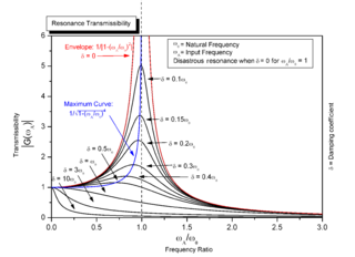
Resonance is the phenomenon, pertaining to oscillatory dynamical systems, wherein amplitude rises are caused by an external force with time-varying amplitude with the same frequency of variation as the natural frequency of the system. The amplitude rises that occur are a result of the fact that applied external forces at the natural frequency entail a net increase in mechanical energy of the system.
In physics, angular acceleration is the time rate of change of angular velocity. Following the two types of angular velocity, spin angular velocity and orbital angular velocity, the respective types of angular acceleration are: spin angular acceleration, involving a rigid body about an axis of rotation intersecting the body's centroid; and orbital angular acceleration, involving a point particle and an external axis.
A gear is a rotating circular machine part having cut teeth or, in the case of a cogwheel or gearwheel, inserted teeth, which mesh with another (compatible) toothed part to transmit rotational power. While doing so, they can change the torque and rotational speed being transmitted and also change the rotational axis of the power being transmitted. The teeth on the two meshing gears all have the same shape.
An epicyclic gear train is a gear reduction assembly consisting of two gears mounted so that the center of one gear revolves around the center of the other. A carrier connects the centers of the two gears and rotates, to carry the planet gear(s) around the sun gear. The planet and sun gears mesh so that their pitch circles roll without slip. If the sun gear is held fixed, then a point on the pitch circle of the planet gear traces an epicycloid curve.
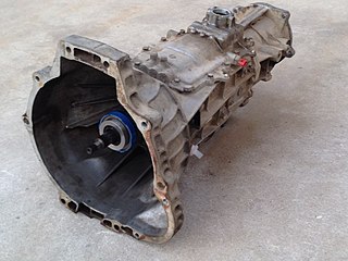
A manual transmission (MT), also known as manual gearbox, standard transmission, or stick shift, is a multi-speed motor vehicle transmission system, where gear changes require the driver to manually select the gears by operating a gear stick and clutch.
In mechanics, virtual work arises in the application of the principle of least action to the study of forces and movement of a mechanical system. The work of a force acting on a particle as it moves along a displacement is different for different displacements. Among all the possible displacements that a particle may follow, called virtual displacements, one will minimize the action. This displacement is therefore the displacement followed by the particle according to the principle of least action.
The work of a force on a particle along a virtual displacement is known as the virtual work.
A non-circular gear (NCG) is a special gear design with special characteristics and purpose. While a regular gear is optimized to transmit torque to another engaged member with minimum noise and wear and with maximum efficiency, a non-circular gear's main objective might be ratio variations, axle displacement oscillations and more. Common applications include textile machines, potentiometers, CVTs, window shade panel drives, mechanical presses and high torque hydraulic engines.
A cycloidal drive or cycloidal speed reducer is a mechanism for reducing the speed of an input shaft by a certain ratio. Cycloidal speed reducers are capable of relatively high ratios in compact sizes with very low backlash.
An idler-wheel is a wheel which serves only to transmit rotation from one shaft to another, in applications where it is undesirable to connect them directly. For example, connecting a motor to the platter of a phonograph, or the crankshaft-to-camshaft gear train of an automobile.
A mechanical amplifier or a mechanical amplifying element is a linkage mechanism that amplifies the magnitude of mechanical quantities such as force, displacement, velocity, acceleration and torque in linear and rotational systems. In some applications, mechanical amplification induced by nature or unintentional oversights in man-made designs can be disastrous, causing situations such as the 1940 Tacoma Narrows Bridge collapse. When employed appropriately, it can help to magnify small mechanical signals for practical applications.
Engine power is the power that an engine can put out. It can be expressed in power units, most commonly kilowatt, pferdestärke, or horsepower. In terms of internal combustion engines, the engine power usually describes the rated power, which is a power output that the engine can maintain over a long period of time according to a certain testing method, for example ISO 1585. In general though, an internal combustion engine has a power take-off shaft, therefore, the rule for shaft power applies to internal combustion engines: Engine power is the product of the engine torque and the crankshaft's angular velocity.
The Ravigneaux gearset is a double planetary gear set, invented by Pol Ravigneaux, who filed a patent application on July 28, 1949, in Neuilly-sur-Seine France. This planetary gear set, commonly used in automatic transmissions, is constructed from two gear pairs, ring–planet and planet–planet.
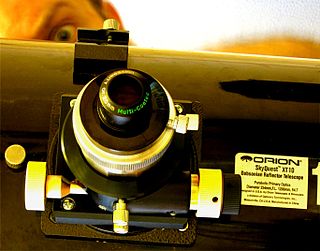
The Dual speed focuser is a focusing mechanism used in precision optics such as advanced amateur astronomical telescopes and laboratory microscopes.
Strain wave gearing is a type of mechanical gear system that uses a flexible spline with external teeth, which is deformed by a rotating elliptical plug to engage with the internal gear teeth of an outer spline.
A variable speed wind turbine is one which is specifically designed to operate over a wide range of rotor speeds. It is in direct contrast to fixed speed wind turbine where the rotor speed is approximately constant. The reason to vary the rotor speed is to capture the maximum aerodynamic power in the wind, as the wind speed varies. The aerodynamic efficiency, or coefficient of power, for a fixed blade pitch angle is obtained by operating the wind turbine at the optimal tip-speed ratio as shown in the following graph.
References
↑ Army Service Corps Training on Mechanical Transport, (1911), Fig. 112
↑ Uicker, J. J.; G. R. Pennock; J. E. Shigley (2003). Theory of Machines and Mechanisms. New York: Oxford University Press.
This page is based on this Wikipedia article Text is available under the CC BY-SA 4.0 license; additional terms may apply. Images, videos and audio are available under their respective licenses.