Poppet valve

Last updated
Poppet valve red.jpg
Poppetvalve.jpg
Poppet valves with valve springs and valve stem collets

A poppet valve (also sometimes called mushroom valve [1] ) is a valve typically used to control the timing and quantity of gas or vapor flow into or out of an engine, but with many other applications.

Contents

It consists of a hole or open-ended chamber, usually round or oval in cross-section, and a plug, usually a disk shape on the end of a shaft known as a valve stem. The working end of this plug, the valve face, is typically ground at a 45° bevel to seal against a corresponding valve seat ground into the rim of the chamber being sealed. The shaft travels through a valve guide to maintain its alignment.

A pressure differential on either side of the valve can assist or impair its performance. In exhaust applications higher pressure against the valve helps to seal it, and in intake applications lower pressure helps open it.

The poppet valve was invented in 1833 by American E.A.G. Young of the Newcastle and Frenchtown Railroad. Young had patented his idea, but the Patent Office fire of 1836 destroyed all records of it. [2]

Etymology

The word poppet shares etymology with "puppet": it is from the Middle English popet ("youth" or "doll"), from Middle French poupette, which is a diminutive of poupée. The use of the word poppet to describe a valve comes from the same word applied to marionettes, which, like the poppet valve, move bodily in response to remote motion transmitted linearly. [3] [4] In the past, "puppet valve" was a synonym for poppet valve; [5] [6] however, this usage of "puppet" is now obsolete.

Design

Piston engine with an automatically actuated intake valve (in red), and a cam-activated exhaust valve (in blue) Poppet valves activated by two mechanisms.gif
Piston engine with an automatically actuated intake valve (in red), and a cam-activated exhaust valve (in blue)

The poppet valve is different from both slide and oscillating valves. Instead of sliding or rocking over a seat to uncover a port, the poppet valve lifts from the seat with a movement perpendicular to the plane of the port. The main advantage of the poppet valve is that it has no movement on the seat, thus requiring no lubrication. [7]

In most cases it is beneficial to have a "balanced poppet" in a direct-acting valve. Less force is needed to move the poppet because all forces on the poppet are nullified by equal and opposite forces. The solenoid coil has to counteract only the spring force. [8]

Poppet valves are best known for their use in internal combustion and steam engines, but are used in general pneumatic and hydraulic circuits where a pulsed flow control is wanted. The pulse can be controlled by a combination of differential pressure and spring load as required.

Presta and Schrader valves used on pneumatic tyres are examples of poppet valves. The Presta valve has no spring and relies on a pressure differential for opening and closing while being inflated.

Poppet valves are employed extensively in the launching of torpedoes from submarines. Many systems use compressed air to expel the torpedo from the tube, and the poppet valve recovers a large quantity of this air (along with a significant amount of seawater) in order to reduce the tell-tale cloud of bubbles that might otherwise betray the boat's submerged position. [9]

Usage in internal combustion engines

Poppet valves in a typical overhead camshaft engine 4StrokeEngine Ortho 3D Small.gif
Poppet valves in a typical overhead camshaft engine

Poppet valves are used in most piston engines to control the flow of intake and exhaust gasses through the cylinder head and into the combustion chamber. The side of the poppet valve which sits inside the combustion chamber is a flat disk, while the other side tapers from the disk shape to a thin cylindrical rod called a "valve stem".

Materials and durability

In a typical modern mass-production engines, the valves are solid and made from steel alloys. However some engines use hollow valves filled with sodium, to improve heat transfer.

Many modern engines use an aluminium cylinder head. Although this provides better heat transfer, it requires steel valve seat inserts to be used; in older cast iron cylinder heads, the valve seats are often part of the cylinder head. A gap of 0.4–0.6 mm (0.016–0.024 in) is present around the valve stem, therefore a valve stem seal is used to prevent combustion gasses escaping through this gap or oil being drawn into the combustion chamber. Typically, a rubber lip-type seal is used. A common symptom of worn valve guides and/or defective oil seals is a puff of blue smoke from the exhaust pipe at times of increased intake manifold vacuum, such as when the throttle is abruptly closed.

Historically, there were two major issues with valves, both of which have been solved by improvements in modern metallurgy. The first was that in early internal combustion engines, high wear rates of valves meant that a valve job to regrind the valves was required at regular intervals. Secondly, lead additives had been used in petrol (gasoline) since the 1920s, to prevent engine knocking and provide lubrication for the valves. Modern materials for the valves (such as stainless steel) and valve seats (such as stellite) allowed for leaded petrol to be phased out in many industrialised countries by the mid-1990s.

Sodium Cooled Exhaust Valves

Exhaust valves are subject to very high temperatures and in extreme high performance applications may be sodium cooled. The valve is hollow and filled with sodium, which melts at a relatively low temperature and, in its liquid state, convects heat away from the hot valve head to the stem where it may be conducted to the cylinder head. Common in second world war piston engines, now only found in high performance engines. [10]

Actuation method

Early engines in the 1890s and 1900s used an "automatic" intake valve, which was opened by the vacuum in the combustion chamber and closed by a light spring. The exhaust valve had to be mechanically driven to open it against the pressure in the cylinder. Use of automatic valves simplified the mechanism, but valve float limited the speed at which the engine could run, and by about 1905 mechanically operated inlet valves were increasingly adopted for vehicle engines.

Mechanical operation is usually by pressing on the end of the valve stem, with a spring generally being used to return the valve to the closed position. At high engine speeds (RPM), the weight of the valvetrain means the valve spring cannot close the valve as quickly enough, leading to valve float or valve bounce. Desmodromic valves use a second rocker arm to mechanically close the valves (instead of using valve springs) and are sometimes used to avoid valve float in engines that operate at high RPM.

In most mass-produced engines, the camshaft(s) control the opening of the valves, via several intermediate mechanisms (such as pushrods, roller rockers and valve lifters). The shape of the cams on the camshaft influence the valve lift and determine the timing of when the valves open.

Number and location of valves

Side-valve engine with Ricardo's turbulent head 01.png
Flathead engine (valve shown in light blue)
Dolomite Sprint Valves Section.jpg
Overhead camshaft engine

Early flathead engines (also called L-head engines) saw the valves located beside to the cylinder(s), in an "upside down" orientation parallel to the cylinder. [11] Although this design made for simplified and cheap construction, the twisting path of the intake and exhaust gasses had major drawbacks for the airflow, which limited engine RPM [12] and could cause the engine block to overheat under sustained heavy load. The flathead design evolved into intake over exhaust (IOE) engine, used in many early motorcycles and several cars. In an IOE engine, the intake valves were located directly above the cylinder (like the later overhead valve engines), however the exhaust valve remains beside the cylinder in an upside down orientation.

These designs were largely replaced by the overhead valve (OHV) engine between 1904 until late-1960s/early-to-mid 1970s, whereby the intake and exhaust valves are both located directly above the cylinder (with the camshaft located at the bottom of the engine). In turn, OHV engines were largely replaced by the overhead camshaft (OHC) engines between 1950s until 1980s. The location of the valves is broadly the same between OHV and OHC engines, however OHC engines saw the camshaft located to the top of the engine with the valves and OHC engines often have more valves per cylinder. Most OHC engines have an extra intake and an extra exhaust valve per cylinder (four-valve cylinder head), compared with the design of two valves per cylinder used by most OHV engines. However some OHC engines have used three or five valves per cylinder.

Usage in steam engines

Balanced poppet valve from U.S. Patent 339,809. High pressure steam enters at A and exits at B. The valve stem D moves up to open the valve discs C PuppetValve.png
Balanced poppet valve from U.S. Patent 339,809. High pressure steam enters at A and exits at B. The valve stem D moves up to open the valve discs C

James Watt was using poppet valves to control the flow of steam into the cylinders of his beam engines in the 1770s. A sectional illustration of Watt's beam engine of 1774 using the device is found in Thurston 1878:98, [13] and Lardner (1840) provides an illustrated description of Watt's use of the poppet valve. [14]

When used in high-pressure applications, for example, as admission valves on steam engines, the same pressure that helps seal poppet valves also contributes significantly to the force required to open them. This has led to the development of the balanced poppet or double beat valve, in which two valve plugs ride on a common stem, with the pressure on one plug largely balancing the pressure on the other. [15] [16] In these valves, the force needed to open the valve is determined by the pressure and the difference between the areas of the two valve openings. Sickels patented a valve gear for double-beat poppet valves in 1842. Criticism was reported in the journal Science in 1889 of equilibrium poppet valves (called by the article the "double or balanced or American puppet valve") in use for paddle steamer engines, that by its nature it must leak 15 percent. [17]

Oscillating poppet valve on one of Chapelon's rebuilt 4-6-2 locomotives. 231-E-41-d.jpg
Oscillating poppet valve on one of Chapelon's rebuilt 4-6-2 locomotives.

Poppet valves have been used on steam locomotives, often in conjunction with Lentz or Caprotti valve gear. British examples include:

Sentinel Waggon Works used poppet valves in their steam wagons and steam locomotives. Reversing was achieved by a simple sliding camshaft system.

Many locomotives in France, particularly those rebuilt to the designs of Andre Chapelon, such as the SNCF 240P, used Lentz oscillating-cam poppet valves, which were operated by the Walschaert valve gear the locomotives were already equipped with.

The poppet valve was also used on the American Pennsylvania Railroad's T1 duplex locomotives, although the valves commonly failed because the locomotives were commonly operated in excess of 160 km/h (100 mph), and the valves were not meant for the stresses of such speeds. The poppet valves also gave the locomotive a distinctive "chuffing" sound.

See also

Related Research Articles

<span class="mw-page-title-main">Sleeve valve</span> Valve mechanism for piston engines

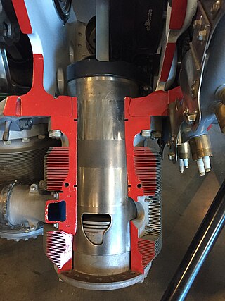
The sleeve valve is a type of valve mechanism for piston engines, distinct from the usual poppet valve. Sleeve valve engines saw use in a number of pre–World War II luxury cars and in the United States in the Willys-Knight car and light truck. They subsequently fell from use due to advances in poppet-valve technology, including sodium cooling, and the Knight system double sleeve engine's tendency to burn a lot of lubricating oil or to seize due to lack of it. The Scottish Argyll company used its own, much simpler and more efficient, single sleeve system (Burt-McCollum) in its cars, a system which, after extensive development, saw substantial use in British aircraft engines of the 1940s, such as the Napier Sabre, Bristol Hercules, Centaurus, and the promising but never mass-produced Rolls-Royce Crecy, only to be supplanted by the jet engines.

<span class="mw-page-title-main">Camshaft</span> Mechanical component that converts rotational motion to reciprocal motion

A camshaft is a shaft that contains a row of pointed cams, in order to convert rotational motion to reciprocating motion. Camshafts are used in piston engines, mechanically controlled ignition systems and early electric motor speed controllers.

<span class="mw-page-title-main">Cylinder head</span> Component of an internal combustion engine

In an internal combustion engine, the cylinder head sits above the cylinders and forms the roof of the combustion chamber. In sidevalve engines, the head is a simple sheet of metal; whereas in more modern overhead valve and overhead camshaft engines, the cylinder head is a more complicated block often containing inlet and exhaust passages, coolant passages, valves, camshafts, spark plugs and fuel injectors. Most straight engines have a single cylinder head shared by all of the cylinders and most V engines have two cylinder heads.

A combustion chamber is part of an internal combustion engine in which the fuel/air mix is burned. For steam engines, the term has also been used for an extension of the firebox which is used to allow a more complete combustion process.

<span class="mw-page-title-main">Valve gear</span> Mechanism for controlling steam flow in a reciprocating steam engine.

The valve gear of a steam engine is the mechanism that operates the inlet and exhaust valves to admit steam into the cylinder and allow exhaust steam to escape, respectively, at the correct points in the cycle. It can also serve as a reversing gear. It is sometimes referred to as the "motion".

<span class="mw-page-title-main">Variable valve timing</span> Process of altering the timing of a valve lift event

Variable valve timing (VVT) is the process of altering the timing of a valve lift event in an internal combustion engine, and is often used to improve performance, fuel economy or emissions. It is increasingly being used in combination with variable valve lift systems. There are many ways in which this can be achieved, ranging from mechanical devices to electro-hydraulic and camless systems. Increasingly strict emissions regulations are causing many automotive manufacturers to use VVT systems.

<span class="mw-page-title-main">Overhead camshaft engine</span> Valvetrain configuration

An overhead camshaft (OHC) engine is a piston engine in which the camshaft is located in the cylinder head above the combustion chamber. This contrasts with earlier overhead valve engines (OHV), where the camshaft is located below the combustion chamber in the engine block.

<span class="mw-page-title-main">Overhead valve engine</span> Type of piston engine valvetrain design

An overhead valve (OHV) engine, sometimes called a pushrod engine, is a piston engine whose valves are located in the cylinder head above the combustion chamber. This contrasts with flathead engines, where the valves were located below the combustion chamber in the engine block.

<span class="mw-page-title-main">Rotary valve</span> Valve where rotation of passages in a plug controls flow direction

A rotary valve is a type of valve in which the rotation of a passage or passages in a transverse plug regulates the flow of liquid or gas through the attached pipes. The common stopcock is the simplest form of rotary valve. Rotary valves have been applied in numerous applications, including:

<span class="mw-page-title-main">Flathead engine</span> A type of four-stroke engine

A flathead engine, also known as a sidevalve engine or valve-in-block engine, is an internal combustion engine with its poppet valves contained within the engine block, instead of in the cylinder head, as in an overhead valve engine.

<span class="mw-page-title-main">Tappet</span> Internal combustion engine part

A tappet is a valve train component which converts rotating motion into linear motion in activating a valve. It is most commonly found in internal combustion engines, which converts the rotating motion of the camshaft into linear motion of intake and exhaust valves, either directly or indirectly.

In a piston engine, the valve timing is the precise timing of the opening and closing of the valves. In an internal combustion engine those are usually poppet valves and in a steam engine they are usually slide valves or piston valves.

<span class="mw-page-title-main">Valvetrain</span> Mechanical system in an internal combustion engine

A valvetrain or valve train is a mechanical system that controls the operation of the intake and exhaust valves in an internal combustion engine. The intake valves control the flow of air/fuel mixture into the combustion chamber, while the exhaust valves control the flow of spent exhaust gasses out of the combustion chamber once combustion is completed.

<span class="mw-page-title-main">IOE engine</span> Type of combustion engines

The intake/inlet over exhaust, or "IOE" engine, known in the US as F-head, is a four-stroke internal combustion engine whose valvetrain comprises OHV inlet valves within the cylinder head and exhaust side-valves within the engine block.

<span class="mw-page-title-main">Uniflow steam engine</span> Type of steam engine

The uniflow type of steam engine uses steam that flows in one direction only in each half of the cylinder. Thermal efficiency is increased by having a temperature gradient along the cylinder. Steam always enters at the hot ends of the cylinder and exhausts through ports at the cooler centre. By this means, the relative heating and cooling of the cylinder walls is reduced.

<span class="mw-page-title-main">Double beat valve</span>

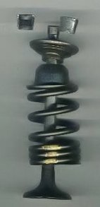
The double-beat valve, drop valve or equilibrium valve is a type of poppet valve arranged to allow it to be opened against a high pressure with a minimum of force. One of its uses is in steam engines to admit steam to the cylinders and to release the exhaust. In stationary steam engines it is usually operated by trip valve gear while in railway locomotives a valve gear such as Caprotti is used.

<span class="mw-page-title-main">Squish (piston engine)</span>

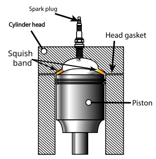
Squish is an effect in internal combustion engines which creates sudden turbulence of the air-fuel mixture as the piston approaches top dead centre (TDC).

<span class="mw-page-title-main">Internal combustion engine</span> Engine in which the combustion of a fuel occurs with an oxidizer in a combustion chamber

An internal combustion engine is a heat engine in which the combustion of a fuel occurs with an oxidizer in a combustion chamber that is an integral part of the working fluid flow circuit. In an internal combustion engine, the expansion of the high-temperature and high-pressure gases produced by combustion applies direct force to some component of the engine. The force is typically applied to pistons, turbine blades, a rotor, or a nozzle. This force moves the component over a distance, transforming chemical energy into kinetic energy which is used to propel, move or power whatever the engine is attached to.


The five-stroke engine is a compound internal combustion engine patented by Gerhard Schmitz in 2000. Schmitz's concept is being developed by Ilmor Engineering. Ilmor's prototype is an internal combustion engine that uses a solid cylinder block with electric motors driving the oil and water cooling pumps. The prototype uses two overhead camshafts with standard poppet valves. The five-stroke prototype engine is turbocharged. The goal of the five-stroke engine is to have higher efficiency with lower fuel use. In order to increase efficiency, a secondary cylinder is added as an expansion processor to extract more energy from the fuel.

References

  1. A.L. Dyke (1921), Dyke's Automobile and Gasoline Encyclopedia, St. Louis, A. L. Dyke, archived from the original on 2016-06-11
  2. White, John H. (1979). A History of the American Locomotive. North Chelmsford, MA: Courier Corporation. p. 145.
  3. "Poppet at Merriam-Webster". Merriam-webster.com. Archived from the original on 2011-10-17. Retrieved 2011-12-06.
  4. "Puppet at Merriam-Webster". Merriam-webster.com. Archived from the original on 2012-01-12. Retrieved 2011-12-06.
  5. "Puppet valve from 1913 Webster's dictionary". Websters-online-dictionary.org. Archived from the original on 2006-02-21. Retrieved 2011-12-06.
  6. "U.S. Patent No. 339809, "Puppet Valve", issued April 13, 1886". Patimg1.uspto.gov. Archived from the original on January 10, 2017. Retrieved 2011-12-06.
  7. Fessenden, Charles H. (1915). Valve Gears. New York: McGraw Hill. pp.  159–168. Archived from the original on 2016-06-03.
  8. Wahl, Philipp (2013). Piston spool valves and poppet valves. Esslingen: Festo AG & Co. KG.
  9. Navy, U. S. (February 2009). Torpedo Tube Manual. ISBN   9781935327639 via Google Books.
  10. Cameron, Kevin (22 April 2020). "Some Facts About Sodium-Filled Valves". Cycle World. Octane Media, LLC. Retrieved 9 July 2023.
  11. "fsoc". fsoc. Archived from the original on 18 March 2018. Retrieved 24 April 2018.
  12. "A Handy Guide to Clinton Engines" (PDF). 1956. p. 2. Archived (PDF) from the original on October 3, 2015. Retrieved October 2, 2015. R. P. M. 2200 — 3600
  13. Thurston, R.H. (1878). A History of the Growth of the Steam Engine. New York: Appleton & Co. pp.  98.
  14. Lardner, Dionysius (1840). The steam engine explained and illustrated. London: Taylor and Walton. pp.  189–91. Archived from the original on 2013-10-04.
  15. Jacques Mouchly, Valve and Valve Gear for Locomotives and Other Engines, U.S. Patent 1,824,830, issued Sept. 29, 1931.
  16. Herman G. Mueller, Steam Engine Valve, U.S. Patent 1,983,803, issued Dec. 11, 1934.
  17. Criticism by E.N. Dickerson in lecture to the Electric Club of New York 17/01/1889, reported by Science vol.13 No.314, Feb 8 1889 p.95 sciencemag.org