Fan (machine)

Last updated
A typical electric fan Quat.JPG
A typical electric fan
A table fan Small Desk Fan 1.jpg
A table fan
Fans are used to force air into low and high bypass jet engines, seen here on a Boeing 777. N7771@GVA;09.09.1995-engine (6083468531).jpg
Fans are used to force air into low and high bypass jet engines, seen here on a Boeing 777.

A fan is a powered machine used to create a flow of air. A fan consists of a rotating arrangement of vanes or blades, generally made of wood, plastic, or metal, which act on the air. The rotating assembly of blades and hub is known as an impeller , rotor , or runner. Usually, it is contained within some form of housing, or case. [1] This may direct the airflow, or increase safety by preventing objects from contacting the fan blades. Most fans are powered by electric motors, but other sources of power may be used, including hydraulic motors, handcranks, and internal combustion engines.

Contents

Mechanically, a fan can be any revolving vane, or vanes used for producing currents of air. Fans produce air flows with high volume and low pressure (although higher than ambient pressure), as opposed to compressors which produce high pressures at a comparatively low volume. A fan blade will often rotate when exposed to an air-fluid stream, and devices that take advantage of this, such as anemometers and wind turbines, often have designs similar to that of a fan.

Typical applications include climate control and personal thermal comfort (e.g., an electric table or floor fan), vehicle engine cooling systems (e.g., in front of a radiator), machinery cooling systems (e.g., inside computers and audio power amplifiers), ventilation, fume extraction, winnowing (e.g., separating chaff from cereal grains), removing dust (e.g. sucking as in a vacuum cleaner), drying (usually in combination with a heat source) and providing draft for a fire. Some fans may be indirectly used for cooling in the case of industrial heat exchangers.

While fans are effective at cooling people, they do not cool air, but rather work by evaporative cooling of sweat and increased heat convection into the surrounding air, due to the airflow from the fans. Thus, fans may become less effective at cooling the body if the surrounding air is near body temperature and contains high humidity.

History

Patent drawing for a Fan Moved by Mechanism, November 27, 1830 Patent, Mechanical Fan, 1830.png
Patent drawing for a Fan Moved by Mechanism, November 27, 1830

The punkah (fan) was used in India about 500 BCE. It was a handheld fan made from bamboo strips or other plant fiber, that could be rotated or fanned to move air. During British rule, the word came to be used by Anglo-Indians to mean a large swinging flat fan, fixed to the ceiling and pulled by a servant called the punkawallah.

For purposes of air conditioning, the Han dynasty craftsman and engineer Ding Huan (fl. 180 CE) invented a manually operated rotary fan with seven wheels that measured 3 m (10 ft) in diameter; in the 8th century, during the Tang dynasty (618–907), the Chinese applied hydraulic power to rotate the fan wheels for air conditioning, while the rotary fan became even more common during the Song dynasty (960–1279). [2] [3]

During the Heian period (794-1185) in Japan, fans adapted the role of symbolizing social class as well as a mechanical role. The tessen, a Japanese fan used in Feudal times, was a dangerous weapon hidden in plain sight in the shape of a regular fan, a weapon used by samurais when katanas were not ideal.

In the 17th century, the experiments of scientists including Otto von Guericke, Robert Hooke and Robert Boyle, established the basic principles of vacuum and airflow. The English architect Sir Christopher Wren applied an early ventilation system in the Houses of Parliament that used bellows to circulate air. Wren's design was the catalyst for much later improvement and innovation. The first rotary fan used in Europe was for mine ventilation during the 16th century, as illustrated by Georg Agricola (1494–1555). [4]

John Theophilus Desaguliers, a British engineer, demonstrated the successful use of a fan system to draw out stagnant air from coal mines in 1727—ventilation was particularly important in coal mines to prevent asphyxiation—and soon afterwards he installed a similar apparatus in Parliament. [5] The civil engineer John Smeaton, and later John Buddle installed reciprocating air pumps in the mines in the North of England, though the machinery was liable to breaking down.

Steam

In 1849 a 6m radius steam-driven fan, designed by William Brunton, was made operational in the Gelly Gaer Colliery of South Wales. The model was exhibited at the Great Exhibition of 1851. Also in 1851 David Boswell Reid, a Scottish doctor, installed four steam-powered fans in the ceiling of St George's Hospital in Liverpool, so that the pressure produced by the fans would force the incoming air upward and through vents in the ceiling. [6] [7] Improvements in the technology were made by James Nasmyth, Frenchman Theophile Guibal and J. R. Waddle. [8]

Electrical

Two c. 1980 box fans Two box fans.jpg
Two c. 1980 box fans

Between 1882 and 1886 Schuyler Wheeler invented a fan powered by electricity. [9] It was commercially marketed by the American firm Crocker & Curtis electric motor company. In 1885 a desktop direct drive electric fan was commercially available by Stout, Meadowcraft & Co. in New York. [10]

In 1882, Philip Diehl developed the world's first electric ceiling mounted fan. During this intense period of innovation, fans powered by alcohol, oil, or kerosene were common around the turn of the 20th century. In 1909, KDK of Japan pioneered the invention of mass-produced electric fans for home use. In the 1920s, industrial advances allowed steel fans to be mass-produced in different shapes, bringing fan prices down and allowing more homeowners to afford them. In the 1930s, the first art deco fan (the "Silver Swan") was designed by Emerson. [11] By the 1940s, Crompton Greaves of India became the world's largest manufacturer of electric ceiling fans mainly for sale in India, Asia, and the Middle East. By the 1950s, table and stand fans were manufactured in bright colors and eye-catching.

Window and central air conditioning in the 1960s caused many companies to discontinue production of fans, [12] but in the mid-1970s, with an increasing awareness of the cost of electricity and the amount of energy used to heat and cool homes, turn-of-the-century styled ceiling fans became popular again as both decorative and energy-efficient.

In 1998 William Fairbank and Walter K. Boyd invented the high-volume low-speed (HVLS) ceiling fan, designed to reduce energy consumption by using long fan blades rotating at low speed to move a relatively large volume of air. [13]

Social implications

Before powered fans were widely accessible, their use related to the social divide between social classes. In Britain and China, they were initially only installed in the buildings of Parliament and in noble homes. In Ancient Egypt (3150 BC), servants were required to fan Pharaohs and important figures.

In parts of the world such as India, where the temperature reaches above 100 °F (38 °C), standing and electric box fans are essential in the business world for customer comfort and an efficient work environment. Fans have become solar powered, energy efficient and battery powered in places with unreliable energy sources.

In South Korea, fans play a part in an old wives tale. Many older South Korean citizens believe in the unscientific and unsupported myth of fan death due to excessive use of an electric fan; Korean electric fans usually turn off after a few hours to protect from fan death.

Typical room electrical fans consume 50 to 100 watts of power, while air-conditioning units use 500 to 4000 watts; fans use less electricity but do not cool the air, simply providing evaporative cooling of sweat. Commercial fans are louder than AC units and can be to disruptively loud. According to the U.S. Consumer Product Safety Commission, reported incidents related to box fans include, fire (266 incidents), potential fire (29 incidents), electrocution (15), electric shock (4 incidents), and electrical hazard (2 incidents). Injuries related to AC units mostly relate to their falling from buildings.

Types

Ceiling fan with a lamp Ceiling fan with lamp.jpg
Ceiling fan with a lamp

Mechanical revolving blade fans are made in a wide range of designs. They are used on the floor, table, desk, or hung from the ceiling (ceiling fan), and can be built into a window, wall, roof, etc. Electronic systems generating significant heat such as computers incorporate fans. Appliances such as hair dryers and space heaters also use fans. They move air in air-conditioning systems and in automotive engines. Fans used for comfort inside a room create a wind chill by increasing the heat transfer coefficient but do not lower temperatures directly. Fans used to cool electrical equipment or in engines or other machines do cool the equipment directly by exhausting hot air into the cooler environment outside of the machine so that cooler air flows in. There are three main types of fans used for moving air, axial, centrifugal (also called radial) and cross flow (also called tangential). The American Society of Mechanical Engineers Performance Testing Code 11 (PTC) [14] provides standard procedures for conducting and reporting tests on fans, including those of the centrifugal, axial, and mixed flows.

Axial-flow

An axial box fan for cooling electrical equipment Luefter y.s.tech pd1270153b-2f.jpg
An axial box fan for cooling electrical equipment

Axial-flow fans have blades that force air to move parallel to the shaft about which the blades rotate. This type of fan is used in a wide variety of applications, ranging from small cooling fans for electronics to the giant fans used in cooling towers. Axial flow fans are applied in air conditioning and industrial process applications. Standard axial flow fans have diameters of 300–400 mm or 1,800–2,000 mm and work under pressures up to 800 Pa. Special types of fans are used as low-pressure compressor stages in aircraft engines. Examples of axial fans are:

Centrifugal

Often called a "squirrel cage" (because of its general similarity in appearance to exercise wheels for pet rodents) or "scroll fan", the centrifugal fan has a moving component (called an impeller) that consists of a central shaft about which a set of blades that form a spiral, or ribs, are positioned. Centrifugal fans blow air at right angles to the intake of the fan and spin the air outwards to the outlet (by deflection and centrifugal force). The impeller rotates, causing air to enter the fan near the shaft and move perpendicularly from the shaft to the opening in the scroll-shaped fan casing. A centrifugal fan produces more pressure for a given air volume, and is used where this is desirable such as in leaf blowers, blowdryers, air mattress inflators, inflatable structures, climate control in air handling units and various industrial purposes. They are typically noisier than comparable axial fans (although some types of centrifugal fans are quieter such as in air handling units).

Cross-flow

Cross-section of a cross-flow fan, from the 1893 patent. The rotation is clockwise. The stream guide F is usually not present in modern implementations. Cross-flow fan schematic patent.png
Cross-section of a cross-flow fan, from the 1893 patent. The rotation is clockwise. The stream guide F is usually not present in modern implementations.
Cross-flow fan Tangential-flow-coloured-labels.png
Cross-flow fan

The cross-flow or tangential fan, sometimes known as a tubular fan, was patented in 1893 by Paul Mortier, [17] [18] and is used extensively in heating, ventilation, and air conditioning (HVAC), especially in ductless split air conditioners. The fan is usually long relative to its diameter, so the flow remains approximately two-dimensional away from the ends. The cross-flow fan uses an impeller with forward-curved blades, placed in a housing consisting of a rear wall and a vortex wall. Unlike radial machines, the main flow moves transversely across the impeller, passing the blading twice.

The flow within a cross-flow fan may be broken up into three distinct regions: a vortex region near the fan discharge, called an eccentric vortex, the through-flow region, and a paddling region directly opposite. Both the vortex and paddling regions are dissipative, and as a result, only a portion of the impeller imparts usable work on the flow. [19] The cross-flow fan, or transverse fan, is thus a two-stage partial admission machine. The popularity of the crossflow fan in HVAC comes from its compactness, shape, quiet operation, and ability to provide a high pressure coefficient. Effectively a rectangular fan in terms of inlet and outlet geometry, the diameter readily scales to fit the available space, and the length is adjustable to meet flow rate requirements for the particular application.

Common household tower fans are also cross-flow fans. [20] Much of the early work focused on developing the cross-flow fan for both high- and low-flow-rate conditions and resulted in numerous patents. Key contributions were made by Coester, Ilberg and Sadeh, Porter and Markland, and Eck.[ when? ] One interesting phenomenon particular to the cross-flow fan is that, as the blades rotate, the local air incidence angle changes. The result is that in certain positions the blades act as compressors (pressure increase), while at other azimuthal locations the blades act as turbines (pressure decrease).

Since the flow both enters and exits the impeller radially, the crossflow fan has been studied and prototyped for potential aircraft applications. [21] Due to the two-dimensional nature of the flow, the fan can be integrated into a wing for use in both thrust production and boundary-layer control. A configuration that utilizes a crossflow fan is located at the wing leading edge is the FanWing design concept initially developed around 1997 and under development by a company of the same name. This design creates lift by deflecting the wake downward due to the rotational direction of the fan, causing a large Magnus force, similar to a spinning leading-edge cylinder. Another configuration utilizing a crossflow fan for thrust and flow control is the propulsive wing, another experimental concept prototype initially developed in the 1990s and 2000s. In this design, the crossflow fan is placed near the trailing edge of a thick wing and draws the air of the wing's suction (top) surface. By doing this, the propulsive wing is nearly stall-free, even at extremely high angles of attack, producing very high lift. However, the fanwing and propulsive wing concepts remain experimental and have only been used for unmanned prototypes.

A cross-flow fan is a centrifugal fan in which the air flows straight through the fan instead of at a right angle. The rotor of a cross-flow fan is covered to create a pressure differential. Cross-flow fans are made to have a double circular arc rear wall with a thick vortex wall that decreases in radial gap. The gap decreases in the direction of the fans impeller rotation. The rear wall has a log-spiral profile while the vortex stabilizer is a horizontal thin wall with rounded edge. [22] The resultant pressure difference allows air to flow straight through the fan, even though the fan blades counter the flow of air on one side of the rotation. Cross-flow fans give airflow along the entire width of the fan; however, they are noisier than ordinary centrifugal fans. Cross-flow fans are often used in ductless air conditioners, air doors, in some types of laptop coolers, in automobile ventilation systems, and for cooling in medium-sized equipment such as photocopiers.

Bladeless fans

An open-face supermarket freezer with an air curtain. Cooling air circulates across the food through the dark slot seen at the rear of the freezer, and through another grille not visible along the front. XinHui Xin Hui Bi Gui Yuan Country Garden Da Run Fa RT-Mart Fresh Food 01.JPG
An open-face supermarket freezer with an air curtain. Cooling air circulates across the food through the dark slot seen at the rear of the freezer, and through another grille not visible along the front.

Dyson Air Multiplier fans introduced to the consumer market in 2009 have popularized a 1981 design by Toshiba that produces a fan that has no exposed fan blades or other visibly moving parts (unless augmented by other features such as for oscillation and directional adjustment). [23] A relatively small quantity of air from a high-pressure-bladed impeller fan, which is contained inside the base rather than exposed, induces the slower flow of a larger airmass through a circular or oval-shaped opening via a low-pressure area created by an airfoil surface shape (the Coandă effect). [23] [24] [25]

Air curtains and air doors also utilize this effect to help retain warm or cool air within an otherwise exposed area that lacks a cover or door. Air curtains are commonly used on open-face dairy, freezer, and vegetable displays to help retain chilled air within the cabinet using a laminar airflow circulated across the display opening. The airflow is typically generated by a mechanical fan of any type described in this article hidden in the base of the display cabinet. HVAC linear slot diffusers also utilize this effect to increase airflow evenly in rooms compared to registers while reducing the energy used by the air handling unit blower.

Installation

Fans may be installed in various ways, according to the application. They are often used in a free installation, without any housing of any kind. There are also some specialised installations.

Ducted fan

In vehicles, a ducted fan is a method of propulsion in which a fan, propeller or rotor is surrounded by an aerodynamic duct or shroud which enhances its performance to create aerodynamic thrust or lift to transport the vehicle.

Jet fan

In ventilation systems a jet fan, also known as an impulse or induction fan, ejects a stream of air which entrains ambient air along with it, in order to circulate the ambient air. The system takes up less space than conventional ventilation ducting and can significantly increase the rates of inflow of fresh air and expulsion of stale air. [26]

Noise

Fans generate noise from the rapid flow of air around blades and obstacles causing vortexes, and from the motor. Fan noise is roughly proportional to the fifth power of fan speed; halving speed reduces noise by about 15 dB. [27]

The perceived loudness of fan noise also depends on the frequency distribution of the noise. This in turn depends on the shape and distribution of moving parts, especially of the blades, and of stationary parts, struts in particular. Like with tire treads, and similar to the principle of acoustic diffusors, an irregular shape and distribution can flatten the noise spectrum, making the noise sound less disturbing. [28] [29] [30]

The inlet shape of the fan can also influence the noise levels generated by the fan. [31]

Fan motor drive methods

Building heating and cooling systems commonly use a squirrel cage fan driven by a belt from a separate electric motor. UMA 2.JPG
Building heating and cooling systems commonly use a squirrel cage fan driven by a belt from a separate electric motor.

Standalone fans are usually powered by an electric motor, often attached directly to the motor's output, with no gears or belts. The motor is either hidden in the fan's center hub or extends behind it. For big industrial fans, three-phase asynchronous motors are commonly used, may be placed near the fan, and drive it through a belt and pulleys. Smaller fans are often powered by shaded pole AC motors, or brushed or brushless DC motors. AC-powered fans usually use mains voltage, while DC-powered fans typically use low voltage, typically 24V, 12V, or 5 V.

In machines with a rotating part, the fan is often connected to it rather than being powered separately. This is commonly seen in motor vehicles with internal combustion engines, large cooling systems, locomotives, and winnowing machines, where the fan is connected to the drive shaft or through a belt and pulleys. Another common configuration is a dual-shaft motor, where one end of the shaft drives a mechanism, while the other has a fan mounted on it to cool the motor itself. Window air conditioners commonly use a dual-shaft fan to operate separate fans for the interior and exterior parts of the device.

Where electrical power or rotating parts are not readily available, fans may be driven by other methods. High-pressure gases such as steam can be used to drive a small turbine, and high-pressure liquids can be used to drive a pelton wheel, either which can provide the rotational drive for a fan.

Large, slow-moving energy sources such as a flowing river can also power a fan using a water wheel and a series of step-down gears or pulleys to increase the rotational speed to that which is required for efficient fan operation.

Solar power

Electric fans used for ventilation may be powered by solar panels instead of mains current. This is an attractive option because once the capital costs of the solar panel have been covered, the resulting electricity is free. Also, electricity is always available when the sun is shining and the fan needs to run. During the absence of electric power solar powered fan is operate the air flowing and maintain environmental condition. A typical example uses a detached 10-watt, 12 in × 12 in (30 cm × 30 cm) solar panel and is supplied with appropriate brackets, cables, and connectors. It can be used to ventilate up to 1,250 square feet (116 m2) of area and can move air at up to 800 cubic feet per minute (400 L/s). Because of the wide availability of 12 V brushless DC electric motors and the convenience of wiring such a low voltage, such fans usually operate on 12 volts.

The detached solar panel is typically installed in the spot which gets most of the sunlight and then connected to the fan mounted as far as 25 feet (8 m) away. Other permanently-mounted and small portable fans include an integrated (non-detachable) solar panel.

See also

Related Research Articles

<span class="mw-page-title-main">Turbopump</span> Pump driven by a gas turbine

A turbopump is a propellant pump with two main components: a rotodynamic pump and a driving gas turbine, usually both mounted on the same shaft, or sometimes geared together. They were initially developed in Germany in the early 1940s. The purpose of a turbopump is to produce a high-pressure fluid for feeding a combustion chamber or other use. While other use cases exist, they are most commonly found in liquid rocket engines.

<span class="mw-page-title-main">Turbofan</span> Airbreathing jet engine designed to provide thrust by driving a fan

A turbofan or fanjet is a type of airbreathing jet engine that is widely used in aircraft propulsion. The word "turbofan" is a combination of the preceding generation engine technology of the turbojet, and a reference to the additional fan stage added. It consists of a gas turbine engine which achieves mechanical energy from combustion, and a ducted fan that uses the mechanical energy from the gas turbine to force air rearwards. Thus, whereas all the air taken in by a turbojet passes through the combustion chamber and turbines, in a turbofan some of that air bypasses these components. A turbofan thus can be thought of as a turbojet being used to drive a ducted fan, with both of these contributing to the thrust.

<span class="mw-page-title-main">Centrifugal compressor</span> Sub-class of dynamic axisymmetric work-absorbing turbomachinery

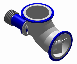
Centrifugal compressors, sometimes called impeller compressors or radial compressors, are a sub-class of dynamic axisymmetric work-absorbing turbomachinery.

<span class="mw-page-title-main">Compressor</span> Machine to increase pressure of gas by reducing its volume

A compressor is a mechanical device that increases the pressure of a gas by reducing its volume. An air compressor is a specific type of gas compressor.

<span class="mw-page-title-main">Ceiling fan</span> Type of fan appliance permanently mounted to the ceiling horizontally

A ceiling fan is a fan mounted on the ceiling of a room or space, usually electrically powered, that uses hub-mounted rotating blades to circulate air. They cool people effectively by increasing air speed. Fans do not reduce air temperature or relative humidity, unlike air-conditioning equipment but create a cooling effect by helping to evaporate sweat and increase heat exchange via convection. Fans add a small amount of heat to the room mainly due to waste heat from the motor, and partially due to friction. Fans use significantly less power than air conditioning as cooling air is thermodynamically expensive. In the winter, fans move warmer air, which naturally rises, back down to occupants. This can affect both thermostat readings and occupants' comfort, thereby improving the energy efficiency of climate control. Many ceiling fan units also double as light fixtures, eliminating the need for separate overhead lights in a room.

<span class="mw-page-title-main">Impeller</span> Rotor used to increase (or decrease in case of turbines) the pressure and flow of a fluid or gas

An impeller, or impellor, is a driven rotor used to increase the pressure and flow of a fluid. It is the opposite of a turbine, which extracts energy from, and reduces the pressure of, a flowing fluid.

<span class="mw-page-title-main">Turbomachinery</span> Machine for exchanging energy with a fluid

Turbomachinery, in mechanical engineering, describes machines that transfer energy between a rotor and a fluid, including both turbines and compressors. While a turbine transfers energy from a fluid to a rotor, a compressor transfers energy from a rotor to a fluid. It is an important application of fluid mechanics.

<span class="mw-page-title-main">Axial-flow pump</span> Type of pump consisting of a propeller in a pipe

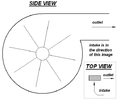
An axial-flow pump, or AFP, is a common type of pump that essentially consists of a propeller in a pipe. The propeller can be driven directly by a sealed motor in the pipe or by electric motor or petrol/diesel engines mounted to the pipe from the outside or by a right-angle drive shaft that pierces the pipe.

A compressor map is a chart which shows the performance of a turbomachinery compressor. This type of compressor is used in gas turbine engines, for supercharging reciprocating engines and for industrial processes, where it is known as a dynamic compressor. A map is created from compressor rig test results or predicted by a special computer program. Alternatively the map of a similar compressor can be suitably scaled. This article is an overview of compressor maps and their different applications and also has detailed explanations of maps for a fan and intermediate and high-pressure compressors from a three-shaft aero-engine as specific examples.

A jet engine performs by converting fuel into thrust. How well it performs is an indication of what proportion of its fuel goes to waste. It transfers heat from burning fuel to air passing through the engine. In doing so it produces thrust work when propelling a vehicle but a lot of the fuel is wasted and only appears as heat. Propulsion engineers aim to minimize the degradation of fuel energy into unusable thermal energy. Increased emphasis on performance improvements for commercial airliners came in the 1970s from the rising cost of fuel.

<span class="mw-page-title-main">Dust collector</span> Industrial machine

A dust collector is a system used to enhance the quality of air released from industrial and commercial processes by collecting dust and other impurities from air or gas. Designed to handle high-volume dust loads, a dust collector system consists of a blower, dust filter, a filter-cleaning system, and a dust receptacle or dust removal system. It is distinguished from air purifiers, which use disposable filters to remove dust.

<span class="mw-page-title-main">Gas turbine engine compressors</span> Engine component

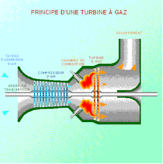
As the name suggests, gas turbine engine compressors provide the compression part of the gas turbine engine thermodynamic cycle. There are three basic categories of gas turbine engine compressor: axial compressor, centrifugal compressor and mixed flow compressor. A fourth, unusual, type is the free-piston gas generator, which combines the functions of compressor and combustion chamber in one unit.

<span class="mw-page-title-main">Centrifugal fan</span> Mechanical fan that forces fluid to move radially outward

A centrifugal fan is a mechanical device for moving air or other gases in a direction at an angle to the incoming fluid. Centrifugal fans often contain a ducted housing to direct outgoing air in a specific direction or across a heat sink; such a fan is also called a blower, blower fan, or squirrel-cage fan. Tiny ones used in computers are sometimes called biscuit blowers. These fans move air from the rotating inlet of the fan to an outlet. They are typically used in ducted applications to either draw air through ductwork/heat exchanger, or push air through similar impellers. Compared to standard axial fans, they can provide similar air movement from a smaller fan package, and overcome higher resistance in air streams.

Industrial fans and blowers are machines whose primary function is to provide and accommodate a large flow of air or gas to various parts of a building or other structures. This is achieved by rotating a number of blades, connected to a hub and shaft, and driven by a motor or turbine. The flow rates of these mechanical fans range from approximately 200 cubic feet (5.7 m3) to 2,000,000 cubic feet (57,000 m3) per minute. A blower is another name for a fan that operates where the resistance to the flow is primarily on the downstream side of the fan.

In fluid dynamics, flow can be decomposed into primary flow plus secondary flow, a relatively weaker flow pattern superimposed on the stronger primary flow pattern. The primary flow is often chosen to be an exact solution to simplified or approximated governing equations, such as potential flow around a wing or geostrophic current or wind on the rotating Earth. In that case, the secondary flow usefully spotlights the effects of complicated real-world terms neglected in those approximated equations. For instance, the consequences of viscosity are spotlighted by secondary flow in the viscous boundary layer, resolving the tea leaf paradox. As another example, if the primary flow is taken to be a balanced flow approximation with net force equated to zero, then the secondary circulation helps spotlight acceleration due to the mild imbalance of forces. A smallness assumption about secondary flow also facilitates linearization.

Between 1936 and 1940 Alan Arnold Griffith designed a series of turbine engines that were built under the direction of Hayne Constant at the Royal Aircraft Establishment (RAE). The designs were advanced for the era, typically featuring a "two-spool" layout with high- and low-pressure compressors that individually had more stages than typical engines of the era. Although advanced, the engines were also difficult to build, and only the much simpler "Freda" design would ever see production, as the Metrovick F.2 and later the Armstrong Siddeley Sapphire. Much of the pioneering work would be later used in Rolls-Royce designs, starting with the hugely successful Rolls-Royce Avon.

A rotodynamic pump is a kinetic machine in which energy is continuously imparted to the pumped fluid by means of a rotating impeller, propeller, or rotor, in contrast to a positive-displacement pump in which a fluid is moved by trapping a fixed amount of fluid and forcing the trapped volume into the pump's discharge. Examples of rotodynamic pumps include adding kinetic energy to a fluid such as by using a centrifugal pump to increase fluid velocity or pressure.

<span class="mw-page-title-main">Components of jet engines</span> Brief description of components needed for jet engines

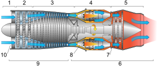
This article briefly describes the components and systems found in jet engines.

Cheng Xu is a Chinese American aerodynamic design engineer and engineering manager. He is a Fellow of the American Society of Mechanical Engineers and a member of the Technical Committee on Energy and Power Systems, IASTED. He also served as a guest editor of International Journal of Rotating Machinery.

<span class="mw-page-title-main">Waddle fan</span> Large centrifugal fans, used to ventilate coal mines

Waddle fans, sometimes incorrectly spelled Waddell, were large centrifugal fans, used to ventilate coal mines.

References

  1. "Fan". Encyclopædia Britannica. Retrieved 2012-05-19.
  2. Needham (1986), Volume 4, Part 2, 99, 134, 151, 233.
  3. Day & McNeil (1996), 210.
  4. Needham, Volume 4, Part 2, 154.
  5. "A Short History of Mechanical Fans". The Worshipful Company of Fan Makers. Archived from the original on December 4, 2013.
  6. Robert Bruegmann. "Central Heating and Ventilation:Origins and Effects on Architectural Design" (PDF). Archived from the original (PDF) on January 21, 2016.
  7. HISTORIC BUILDING ENGINEERING SYSTEMS & EQUIPMENT HEATING & VENTILATION, By Brian Roberts, CIBSE Heritage Group
  8. Cory, William (2010). Fans and Ventilation: A practical guide. Elsevier. ISBN   978-0-08-053158-8.
  9. "B. A. C. (Before Air Conditioning)" (PDF). New Orleans Bar Association. Archived from the original (PDF) on 2012-09-03. Retrieved 2010-07-19.
  10. Scientific American. Munn & Company. 1885-07-18. p. 37.
  11. "Emerson Silver Swan Fan | Missouri Historical Society".
  12. Fancollectors.org – A Brief History of Fans Information Provided by Steve Cunningham – retrieved July 5, 2010.
  13. Industrial Fan Designer Finds Niche in Energy Efficiency – Automation and Control, By David Greenfield, December 20, 2010, Blog on Design News, Information provided by Dianna Huff – retrieved May 18, 2011.
  14. ASME PTC 11 – Fans.
  15. MacEachern, Ruth (24 October 2022). "Do extractor fans cost a lot to run?". EnviroVent.
  16. "Heat loss through Continuous Running Fans". BuildHub.org.uk. 8 November 2019.
  17. Paul Mortier. Fan or Blowing apparatus. US Pat. No. 507,445
  18. "Everything You Should Know About Cross Flow Fan - PBM Motor and Fan". PBM. Retrieved 2023-11-29.
  19. Porter, A. M.; Markland, E. (December 1970). "A Study of the Cross Flow Fan". Journal of Mechanical Engineering Science. 12 (6): 421–431. doi:10.1243/JMES_JOUR_1970_012_071_02. ISSN   0022-2542.
  20. "Tangential Fans: Introduction and Working Principle Discussed". Sofasco Fans. Retrieved 2023-11-29.
  21. Himeur, Rania M.; Khelladi, Sofiane; Ait Chikh, Mohamed Abdessamed; Vanaei, Hamid Reza; Belaidi, Idir; Bakir, Farid (January 2022). "Towards an Accurate Aerodynamic Performance Analysis Methodology of Cross-Flow Fans". Energies. 15 (14): 5134. doi: 10.3390/en15145134 . ISSN   1996-1073.
  22. Casarsa, L.; Giannattasio, P. (September 2011). "Experimental study of the three-dimensional flow field in cross-flow fans". Experimental Thermal and Fluid Science. 35 (6): 948–959. doi:10.1016/j.expthermflusci.2011.01.015. ISSN   0894-1777.
  23. 1 2 Wallop, Harry (October 20, 2009). "Dyson fan: was it invented 30 years ago?" . The Daily Telegraph. London. Archived from the original on 2022-01-12.
  24. Wilson, Mark (October 12, 2009). "Dyson Air Multiplier Review: Making a $300 Fan Takes Cojones". Gizmodo .
  25. Biggs, John (October 12, 2009). "Video Review: The Dyson Air Multiplier". TechCrunch . Archived from the original on March 15, 2011. Retrieved May 22, 2011.
  26. Jet Fan Systems Archived 2022-02-24 at the Wayback Machine , Syetemair, 2017. (retrieved 22 March 2022)
  27. UK Health and Safety Executive: Top 10 noise control techniques
  28. "The Thermodynamics Behind the Mac Pro". Popular Mechanics. 10 December 2019. Retrieved 17 December 2019.
  29. Tae Kim. "Reduction of Tonal Propeller Noise by Means of Uneven Blade Spacing". p. 4
  30. M. Boltezar; M. Mesaric; A. Kuhelj. "The influence of uneven blade spacing on the SPL and noise spectra radiated from radial fans".
  31. "UltraFlo Fluid Dynamic Bearing Fans for Thin Laptop Computers".