Rotary valve

Last updated
A rotary valve in default (A) and engaged (B) positions. 1. input airflow; 2. output airflow; 3. valve tubing; 4. valve casing; 5. internal rotor; 6. valve ports, or "knuckles"; 7. rotor spindle. Brass instrument rotary valve diagram.svg
A rotary valve in default (A) and engaged (B) positions. 1. input airflow; 2. output airflow; 3. valve tubing; 4. valve casing; 5. internal rotor; 6. valve ports, or "knuckles"; 7. rotor spindle.

A rotary valve (also called rotary-motion valve) is a type of valve in which the rotation of a passage or passages in a transverse plug regulates the flow of liquid or gas through the attached pipes. [1] The common stopcock is the simplest form of rotary valve. Rotary valves have been applied in numerous applications, including:

Contents

Use in brass instruments

Rotary valve for a double horn Rotor valve.svg
Rotary valve for a double horn

In the context of brass instruments, rotary valves are found on horns, trumpets, trombones, flugelhorns, and tubas. The cornet derived from the posthorn, by applying rotary valves to it in the 1820s in France. [3] An alternative to a rotary valve trumpet would be piston valve trumpet. [4] Many European trumpet players tend to favor rotary valves.[ citation needed ]

Trombone F attachment valves are usually rotary, with several variations on the basic design also in use, such as the Thayer axial flow valve and the Hagmann valve.

Rotary valve was first applied to the horn in 1824 by Nathan Adams (1783-1864) of Boston and patented in 1835 by Joseph Riedl. [5]

Tuba with 4 rotary valves, by Yamaha Yamaha Contrabass tuba YBB-641.tif
Tuba with 4 rotary valves, by Yamaha

Use in industry

Rotary valves for industrial manufacturing are often used in bulk material handling, dust collection or pneumatic conveying systems, depending on the application. The valve is used to regulate the flow of a product or material by maintaining a consistent flow rate suited to the process. Controlling the flow of material helps to prevent issues such as jamming, material leakage and damage to the valve itself. [6] Typical applications are for feeding a weighed hopper or for feeding a mill that can be clogged by the product.

Valves are part of the material exchange process and work in metering or feeding applications, function as rotary airlocks, or provide a combination of airlock and metering functions.

A rotary valve in the pharmaceutical, chemical and food industry is used to dose and feed solid bulk products within the processes. Valves are also commonly used in construction, plastics, recycling, agriculture and forestry, or wherever material needs to be safely and efficiently conveyed from one point to another.

An airlock-type rotary valve receives and dispenses material from two chambers with different pressure levels. They seal air flow between the valve’s inlet and outlet to maintain a consistent pressure differential, which promotes efficient material flow. The valve’s pressurized chamber prevents foreign material from infiltrating the housing and keeps conveyed material from escaping the system. [7]

Use in engine design

Four-stroke engines

Itala rotary valve engine (1912). Itala rotary valve strokes.jpg
Itala rotary valve engine (1912).
Italarotary valve cooling (1919). Itala rotary valve cooling.jpg
Italarotary valve cooling (1919).
Darracq rotary-valve engine (c.1919)

The rotary valve combustion engine possesses several significant advantages over the conventional assemblies, including significantly higher compression ratios and rpm, meaning more power, a much more compact and light-weight cylinder head, and reduced complexity, meaning higher reliability and lower cost. As inlet and exhaust are usually combined, special attention should be given to valve cooling to avoid engine knocking.

Rotary valves have been used in several different engine designs. In Britain, the National Engine Company Ltd advertised its rotary valve engine for use in early aircraft, at a time when poppet valves were prone to failure by sticking or burning. [8]

In the end of 1930s, Frank Aspin developed a design with a rotary valve that rotated on the same axis as the cylinder bore, but with limited success. [9]

US company Coates International Ltd has developed a spherical rotary valve for internal combustion engines which replaces the poppet valve system. This particular design is four-stroke, with the rotary valves operated by overhead shafts in lieu of overhead camshafts (i.e. in line with a bank of cylinders). The first sale of such an engine was part of a natural gas engine-generator. [10]

Rotary valves are potentially highly suitable for high-revving engines, such as those used in racing sportscars and F1 racing cars, on which traditional poppet valves with springs can fail due to valve float and spring resonance and where the desmodromic valve gear is too heavy, large in size and too complex to time and design properly. Rotary valves could allow for a more compact and lightweight cylinder head design. They rotate at half engine speed (or one quarter) and lack the inertia forces of reciprocating valve mechanisms. This allows for higher engine speeds, offering approximately perhaps 10% more power. The 1980s MGN W12 F1 engine used rotary valves but never raced. Between 2002 and 2004 the Australian developer Bishop Innovation and Mercedes-Ilmor tested rotary valves for a F1 V10 engine. [11]

Bishop Innovations' patent for the rotary valve engine was bought out by BRV Pty Ltd, owned by Tony Wallis, one of the valves original designers. BRV has constructed several functional motors using the rotary valve technology, such as a Honda CRF 450, which had greater torque at both low(17% increase) and high (9% increase) engine speeds, and also produced more brake horsepower up to around 30% more at functional engine speeds. [11] The engine was also considerably smaller and lighter, as the cylinder head assembly was not as large.

A company in the UK called Roton Engine Developments made some progress in 2005 with a two-rotor (one for inlet and one for exhaust) single-cylinder Husaberg motorcycle engine. They filed patents and got an example running in 2006, but were backed by MG Rover which subsequently went bust, leaving Roton without enough funds to continue. The designs surfaced some years later in Australia with Engine Developments Australia Pty Ltd. A prototype casting was produced in 2013 on a Kawasaki Ninja 300 parallel twin unit. This unit is still in development phase at the time of writing but is significant as it has the potential to run much higher compression ratios than even other rotary valve engines due to a significant but undisclosed new cooling method of the combustion chamber and the ability to eliminate the throttle completely, making it vastly more economical at lower engine speeds, so it is claimed.

A proven completely successful automotive rotary valve engine has been built by the late Ralph Ogden Watson of Auckland New Zealand, during 1989. The car has covered many trouble free miles from that date and remains in use. [12] [13] Success was achieved as a result of Watson's academic approach to the problem of sealing, his study of previous designs, and his particular combination of knowledge of materials, machining skills, experience with engines, perseverance and realistic expectations. No new or only recently available materials were involved. Full details of the development of the car and engine appear in the book "Ralph Watson Special Engineer," first published 2004, ISBN O-476-01371-2 and available free and easily searchable, on the internet as of 2020. The car is currently owned by Ray Ferner.

Two-stroke engines

A rotary valve in the form of a flat disc, also known as a disc valve, is used in two-stroke motorcycle engines, where the arrangement helps to prevent reverse flow back into the intake port during the compression stroke. Austrian engine manufacturer Rotax used rotary intake valves in their now out-of-production 64 hp (48 kW) Rotax 532 two-stroke engine design and continues to use rotary intake valves in the 532's successor, the current-production 64 hp (48 kW) Rotax 582. [14]

Use in production engines

UK company RCV Engines Ltd uses rotating cylinder liner technology as a specialized form of rotary valve in some of their four-stroke model engine and small-engine line-up. [15] [16] RCV also use horizontal and vertical rotary valves in four-stroke engines in their current range of engines. [17]

RCV have developed a 125cc rotating cylinder liner engine, incorporating a rotating valve in the cylinder liner, for scooter applications. PGO Scooters of Taiwan were working with RCV in developing the engine for their applications. [18]

The Suzuki RG500 "Gamma" was powered by a two-stroke, rotary valve, twin crank, square four engine displacing 498 cubic centimeters. The power output was 93.7 brake horsepower (69.9 kW) at 9,500 RPM.

Use in chromatography

Rotary valves are used for loading samples on columns used for liquid or gas chromatography. The valves used in these methods are usually 6-port, 2-position rotary valves.

See also

Related Research Articles

<span class="mw-page-title-main">Piston</span> Machine component used to compress or contain expanding fluids in a cylinder

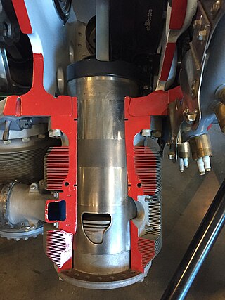
A piston is a component of reciprocating engines, reciprocating pumps, gas compressors, hydraulic cylinders and pneumatic cylinders, among other similar mechanisms. It is the moving component that is contained by a cylinder and is made gas-tight by piston rings. In an engine, its purpose is to transfer force from expanding gas in the cylinder to the crankshaft via a piston rod and/or connecting rod. In a pump, the function is reversed and force is transferred from the crankshaft to the piston for the purpose of compressing or ejecting the fluid in the cylinder. In some engines, the piston also acts as a valve by covering and uncovering ports in the cylinder.

<span class="mw-page-title-main">Reciprocating engine</span> Engine utilising one or more reciprocating pistons

A reciprocating engine, also often known as a piston engine, is typically a heat engine that uses one or more reciprocating pistons to convert high temperature and high pressure into a rotating motion. This article describes the common features of all types. The main types are: the internal combustion engine, used extensively in motor vehicles; the steam engine, the mainstay of the Industrial Revolution; and the Stirling engine for niche applications. Internal combustion engines are further classified in two ways: either a spark-ignition (SI) engine, where the spark plug initiates the combustion; or a compression-ignition (CI) engine, where the air within the cylinder is compressed, thus heating it, so that the heated air ignites fuel that is injected then or earlier.

<span class="mw-page-title-main">Steam engine</span> Engine that uses steam to perform mechanical work

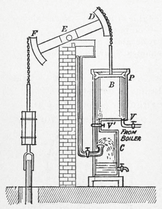
A steam engine is a heat engine that performs mechanical work using steam as its working fluid. The steam engine uses the force produced by steam pressure to push a piston back and forth inside a cylinder. This pushing force can be transformed, by a connecting rod and crank, into rotational force for work. The term "steam engine" is most commonly applied to reciprocating engines as just described, although some authorities have also referred to the steam turbine and devices such as Hero's aeolipile as "steam engines". The essential feature of steam engines is that they are external combustion engines, where the working fluid is separated from the combustion products. The ideal thermodynamic cycle used to analyze this process is called the Rankine cycle. In general usage, the term steam engine can refer to either complete steam plants, such as railway steam locomotives and portable engines, or may refer to the piston or turbine machinery alone, as in the beam engine and stationary steam engine.

<span class="mw-page-title-main">Two-stroke engine</span> Internal combustion engine type

A two-strokeengine is a type of internal combustion engine that completes a power cycle with two strokes of the piston in one revolution of the crankshaft. A four-stroke engine requires four strokes of the piston to complete a power cycle in two crankshaft revolutions. In a two-stroke engine, the end of the combustion stroke and the beginning of the compression stroke happen simultaneously, with the intake and exhaust functions occurring at the same time.

<span class="mw-page-title-main">Sleeve valve</span> Valve mechanism for piston engines

The sleeve valve is a type of valve mechanism for piston engines, distinct from the usual poppet valve. Sleeve valve engines saw use in a number of pre–World War II luxury cars and in the United States in the Willys-Knight car and light truck. They subsequently fell from use due to advances in poppet-valve technology, including sodium cooling, and the Knight system double sleeve engine's tendency to burn a lot of lubricating oil or to seize due to lack of it. The Scottish Argyll company used its own, much simpler and more efficient, single sleeve system (Burt-McCollum) in its cars, a system which, after extensive development, saw substantial use in British aircraft engines of the 1940s, such as the Napier Sabre, Bristol Hercules, Centaurus, and the promising but never mass-produced Rolls-Royce Crecy, only to be supplanted by the jet engines.

<span class="mw-page-title-main">Poppet valve</span> Type of valve

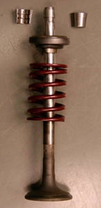
A poppet valve is a valve typically used to control the timing and quantity of petrol (gas) or vapour flow into or out of an engine, but with many other applications.

<span class="mw-page-title-main">Four-stroke engine</span> Internal combustion engine type

A four-strokeengine is an internal combustion (IC) engine in which the piston completes four separate strokes while turning the crankshaft. A stroke refers to the full travel of the piston along the cylinder, in either direction. The four separate strokes are termed:

  1. Intake: Also known as induction or suction. This stroke of the piston begins at top dead center (T.D.C.) and ends at bottom dead center (B.D.C.). In this stroke the intake valve must be in the open position while the piston pulls an air-fuel mixture into the cylinder by producing a partial vacuum in the cylinder through its downward motion.
  2. Compression: This stroke begins at B.D.C, or just at the end of the suction stroke, and ends at T.D.C. In this stroke the piston compresses the air-fuel mixture in preparation for ignition during the power stroke (below). Both the intake and exhaust valves are closed during this stage.
  3. Combustion: Also known as power or ignition. This is the start of the second revolution of the four stroke cycle. At this point the crankshaft has completed a full 360 degree revolution. While the piston is at T.D.C. the compressed air-fuel mixture is ignited by a spark plug or by heat generated by high compression, forcefully returning the piston to B.D.C. This stroke produces mechanical work from the engine to turn the crankshaft.
  4. Exhaust: Also known as outlet. During the exhaust stroke, the piston, once again, returns from B.D.C. to T.D.C. while the exhaust valve is open. This action expels the spent air-fuel mixture through the exhaust port.
<span class="mw-page-title-main">Valve gear</span> Mechanism for controlling steam flow in a reciprocating steam engine.

The valve gear of a steam engine is the mechanism that operates the inlet and exhaust valves to admit steam into the cylinder and allow exhaust steam to escape, respectively, at the correct points in the cycle. It can also serve as a reversing gear. It is sometimes referred to as the "motion".

<span class="mw-page-title-main">Connecting rod</span> Piston engine component which connects the piston to the crankshaft

A connecting rod, also called a 'con rod', is the part of a piston engine which connects the piston to the crankshaft. Together with the crank, the connecting rod converts the reciprocating motion of the piston into the rotation of the crankshaft. The connecting rod is required to transmit the compressive and tensile forces from the piston. In its most common form, in an internal combustion engine, it allows pivoting on the piston end and rotation on the shaft end.

<span class="mw-page-title-main">Reed valve</span> Type of check valve

Reed valves are a type of check valve which restrict the flow of fluids to a single direction, opening and closing under changing pressure on each face. Modern versions often consist of flexible metal or composite materials.

<span class="mw-page-title-main">Motorcycle engine</span> Engine that powers a motorcycle

A motorcycle engine is an engine that powers a motorcycle. Motorcycle engines are typically two-stroke or four-stroke internal combustion engines, but other engine types, such as Wankels and electric motors, have been used.

In a piston engine, the valve timing is the precise timing of the opening and closing of the valves. In an internal combustion engine those are usually poppet valves and in a steam engine they are usually slide valves or piston valves.

A swing-piston engine is a type of internal combustion engine in which the pistons move in a circular motion inside a ring-shaped "cylinder", moving closer and further from each other to provide compression and expansion. Generally two sets of pistons are used, geared to move in a fixed relationship as they rotate around the cylinder. In some versions the pistons oscillate around a fixed center, as opposed to rotating around the entire engine. The design has also been referred to as a oscillating piston engine, vibratory engine when the pistons oscillate instead of rotate, or toroidal engine based on the shape of the "cylinder".

<span class="mw-page-title-main">Valvetrain</span> Mechanical system in an internal combustion engine

A valvetrain or valve train is a mechanical system that controls the operation of the intake and exhaust valves in an internal combustion engine. The intake valves control the flow of air/fuel mixture into the combustion chamber, while the exhaust valves control the flow of spent exhaust gasses out of the combustion chamber once combustion is completed.

A throttle is a mechanism by which fluid flow is managed by constriction or obstruction.

<span class="mw-page-title-main">Hydraulic motor</span> Machine converting flow into rotation

A hydraulic motor is a mechanical actuator that converts hydraulic pressure and flow into torque and angular displacement (rotation). The hydraulic motor is the rotary counterpart of the hydraulic cylinder as a linear actuator. Most broadly, the category of devices called hydraulic motors has sometimes included those that run on hydropower but in today's terminology the name usually refers more specifically to motors that use hydraulic fluid as part of closed hydraulic circuits in modern hydraulic machinery.

<span class="mw-page-title-main">Uniflow steam engine</span> Type of steam engine

The uniflow type of steam engine uses steam that flows in one direction only in each half of the cylinder. Thermal efficiency is increased by having a temperature gradient along the cylinder. Steam always enters at the hot ends of the cylinder and exhausts through ports at the cooler centre. By this means, the relative heating and cooling of the cylinder walls is reduced.

<span class="mw-page-title-main">Single- and double-acting cylinders</span> Classification of reciprocating engine cylinders

In mechanical engineering, the cylinders of reciprocating engines are often classified by whether they are single- or double-acting, depending on how the working fluid acts on the piston.

<span class="mw-page-title-main">High-speed steam engine</span> Steam engine designed to run at comparatively high speed

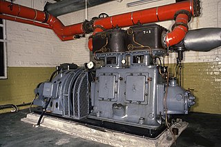
High-speed steam engines were one of the final developments of the stationary steam engine. They ran at a high speed, of several hundred rpm, which was needed by tasks such as electricity generation.

<span class="mw-page-title-main">Internal combustion engine</span> Engine in which the combustion of a fuel occurs with an oxidizer in a combustion chamber

An internal combustion engine is a heat engine in which the combustion of a fuel occurs with an oxidizer in a combustion chamber that is an integral part of the working fluid flow circuit. In an internal combustion engine, the expansion of the high-temperature and high-pressure gases produced by combustion applies direct force to some component of the engine. The force is typically applied to pistons, turbine blades, a rotor, or a nozzle. This force moves the component over a distance, transforming chemical energy into kinetic energy which is used to propel, move or power whatever the engine is attached to.

References

  1. Skousen, Philip (2004). Valve Handbook (2d ed.). McGraw Hill Professional. p. 11. ISBN   9780071501422.
  2. "Corliss' Demonstration Model of a Steam Engine Valve Gear and Spring Dash Pot". National Museum of American History . Retrieved February 24, 2022.
  3. Griffiths, Paul (2006). The New Penguin Dictionary of Music. London: Penguin Books. p. 195. ISBN   0-141-00925-X.
  4. Steen, Alecia (January 6, 2022). "Trumpet Vs. Cornet: What's The Real Difference?". primesound.org. Retrieved February 24, 2022.
  5. Ericson, John (1992). "Early Valve Designs". Arizona State University . Retrieved February 24, 2022.
  6. Thompson, Megan. "Don't overstuff your pockets and 3 other material flow tips". ACS Valves. Retrieved 21 July 2021.
  7. Bowman, Paul. "Are rotary airlocks supposed to leak?". ACS Valves. Retrieved 21 July 2021.
  8. Flight magazine, April 1911
  9. Institution of Mechanical Engineers (2011). Internal Combustion Engines: Improving Performance, Fuel Economy and Emissions. Woodhead Publishing. p. 135. ISBN   978-0-85709-205-2.
  10. Coates International Accessed on 3rd Mar 2011
  11. 1 2 Wallis, Tony (2007). "The Bishop Rotary Valve" (PDF) (Special ed.). AutoTechnology Magazine. Retrieved 2011-12-26.
  12. 2020 Leadfoot Festival competitors
  13. Youtube: Watson-BSA Special
  14. Raisner, William: LEAF catalog, pages 6-105. Leading Edge Airfoils, 1995.
  15. RCV. "RCV Engines Ltd - UK (India – AutoExpo 2004)" (PDF). Archived from the original (PDF) on 2011-11-12. Retrieved 2012-01-03.
  16. Keith Lawes. "The Rotating Cylinder Valve 4-stroke Engine (SAE Paper 2002-32-1828)" (PDF). Archived from the original (PDF) on 2011-11-12. Retrieved 2012-01-03.
  17. "rcv_engines_ltd". Rcvengines.com. Retrieved 2014-04-18.
  18. Jeremy Korzeniewski. "PGO working on rotary valve scooter engine". Green.autoblog.com. Retrieved 2014-04-18.