Condensing steam locomotive

Last updated
Mersey Railway locomotive Cecil Raikes, showing the prominent exhaust pipes leading back to the water tanks Mersey Railway No. 5 Cecil Raikes.jpg
Mersey Railway locomotive Cecil Raikes, showing the prominent exhaust pipes leading back to the water tanks

A condensing steam locomotive is a type of locomotive designed to recover exhaust steam, either in order to improve range between taking on boiler water, or to reduce emission of steam inside enclosed spaces. The apparatus takes the exhaust steam that would normally be used to produce a draft for the firebox, and routes it through a heat exchanger, into the boiler water tanks. Installations vary depending on the purpose, design and the type of locomotive to which it is fitted. It differs from the usual closed cycle condensing steam engine, in that the function of the condenser is primarily either to recover water, or to avoid excessive emissions to the atmosphere, rather than maintaining a vacuum to improve both efficiency and power.

Contents

Thermodynamics

Unlike the surface condenser often used on a steam turbine or marine steam engine, the condensing apparatus on a steam locomotive does not normally increase the power output, rather it decreases due to a reduction of airflow to the firebox that heats the steam boiler. In fact it may reduce it considerably. Condensing the steam from a high volume gas to a low volume liquid causes a significant pressure drop at the exhaust, which usually would add additional power in most steam engines. Whilst more power is potentially available by expanding down to a vacuum, the power output is actually greatly reduced compared to a conventional steam locomotive on account of the lower air flow through the firebox, as there is now no waste steam to eject into the firebox exhaust in order to pull more air into the firebox air intake. In order to produce similar power, air to the firebox must be provided by a steam driven or mechanically driven fan. This often cancels out any improvement in efficiency.

The temperature of the exhaust steam is greater than typical stationary or ship-based steam plant of similar power due to having fewer waste recovery stages, as ships often have a compound steam engine with an additional low pressure stage or even a low speed turbine. Waste heat on modern steam plants is often recovered using heat exchangers. However, condensing locomotives do not have this benefit due to the waste heat being expelled to the surrounding air and not being recovered, and therefore none of the energy in the waste steam is recovered to do mechanical work. In many conditions the temperature gradient is often much worse due to using air instead of having an abundant source of cooling water as naval or stationary steam power plants have. The Anderson condensing system significantly reduces these losses by only partially cooling the waste steam before compressing it into condensate, then pumping the high temperature condensate back into the boiler in order to recover the unused waste heat. This greatly reduces energy waste.

Because of the relatively high temperature in a locomotive condenser and the rejection of the heat to the air, the potential improvement in thermal efficiency expected from including the condenser in the cycle is not usually realised within the space constraints of a typical locomotive. Indeed, losses due to viscous friction in the condenser piping, and having to pump the condensate back into the boiler is likely to reduce the power output over what was achievable from simply venting to atmosphere.

These restrictions do not apply to marine or stationary steam engines due to not having size or weight restrictions. Ships often had massive waste steam recovery systems, such as the 400 ton waste steam turbine used to recover very low 6psi waste steam on the Titanic and its sister ships. [1] This is several times the weight of an entire locomotive, and so is clearly not feasible as a form of waste steam recovery for locomotives.

Exhaust draught

A drawback of condensing the exhaust steam is that it is no longer available to draw the fire, by use of the blastpipe. The draught must thus be generated instead by a steam-driven fan. [2] Where possible, this has been arranged to use exhaust steam, although in some cases live steam was required, with extra steam and thus fuel consumption.

Types of condenser

Steam locomotive condensers may be water-cooled or air-cooled.

Water tank condenser

Here, the exhaust steam is blown into cold water in the locomotive's water tanks. A non-return system must be fitted, to prevent water from the tanks being drawn into the cylinders when the steam is shut off. This system was mainly used for locomotives working in tunnels.

Air condenser

Here, the exhaust steam is blown into an air-cooled radiator, similar to that used for the cooling system of an internal combustion engine. This system was used on small tram engines (where the condenser was mounted on the roof) and on large tender engines (where the condenser was mounted in the tender).

Anderson system

The Anderson condensing system [3] uses an air-cooled condenser but the steam is only partially condensed to form an aerosol of water droplets in steam. This aerosol is then liquified by pressure, using a specially-designed boiler feed pump. A fuel saving of nearly 30% (compared with exhausting to the atmosphere) was claimed for the Anderson system but this seems paradoxical. One would expect a higher fuel consumption because of the power required to compress the aerosol.

The reason this is possible is due to Carnot's theorem, which states that pumping heat requires less energy than producing the heat itself.

A similar effect known as Vapor-compression desalination was later used for desalination of water. Instead of returning the condensate water to the boiler, the hot compressed condensate is passed through a heat exchanger to return heat to the boiler, then released as clean drinking water. It is one of the most efficient processes used to desalinate water. [4]

Purpose

There are two usual reasons for fitting condensing equipment - reducing exhaust emissions and increasing range.

Reduced exhaust emissions

Underground railways

Metropolitan Railway A Class. Note the large valves in the steam return pipes, switching between condensing and non-condensing modes. Metropolitan Railway Steam Locomotive, London Transport Museum.jpg
Metropolitan Railway A Class. Note the large valves in the steam return pipes, switching between condensing and non-condensing modes.

Originally developed for the Metropolitan Railway to allow their locomotives to work the tunnels of the London Underground. This system was devised by Daniel Gooch and developed by Beyer, Peacock & Company. Steam is diverted from the exhaust steam pipes into the water tanks via condensing pipes within the same tanks. [5] The water in the tanks could quickly heat up near boiling point, reducing the condensing effect on the exhaust steam. It was not unknown for the tanks to be emptied and refilled with cold water on a regular basis. Ordinary injectors will not work with hot water [5] (until hot-water injectors were developed) so condensing locomotives were usually fitted with axle-driven boiler feedwater pumps. When not working in tunnels, the steam was directed to the blast pipe and up the chimney in the usual way.

Roadside tramways

In Britain, locomotives working on roadside steam tramways were required by law to have condensers. Water tank condensers (as above) were sometimes used but air-condensers were more common. A steam tram engine usually had a full-length roof and this was surmounted by a nest of air-cooled copper tubes in which the exhaust steam was condensed. Kitson & Company made many engines of this type. The system was satisfactory for tram engines (which were very low-powered) but would not have worked for larger railway locomotives.

Increased range

Generally this was a more sophisticated installation that used forced air cooling to condense the exhaust steam. The system was intended to reduce the problems of getting enough water to steam locomotives running through desert and very arid areas, e.g. South Africa. (See below)

Locomotives fitted with a condensing apparatus

South African Class 25 Note the extremely large tender, with side louvres to cool the condensers SAR Class 25 3511 (4-8-4).JPG
South African Class 25 Note the extremely large tender, with side louvres to cool the condensers
South African Class 25 SAR Class 25 3511 (4-8-4) Banjoface.JPG
South African Class 25

With water tank condensers

With tender air condensers

See also

Related Research Articles

<span class="mw-page-title-main">Steam engine</span> Engine that uses steam to perform mechanical work

A steam engine is a heat engine that performs mechanical work using steam as its working fluid. The steam engine uses the force produced by steam pressure to push a piston back and forth inside a cylinder. This pushing force can be transformed, by a connecting rod and crank, into rotational force for work. The term "steam engine" is generally applied only to reciprocating engines as just described, not to the steam turbine. Steam engines are external combustion engines, where the working fluid is separated from the combustion products. The ideal thermodynamic cycle used to analyze this process is called the Rankine cycle. In general usage, the term steam engine can refer to either complete steam plants, such as railway steam locomotives and portable engines, or may refer to the piston or turbine machinery alone, as in the beam engine and stationary steam engine.

<span class="mw-page-title-main">Steam locomotive</span> Railway locomotive that produces its pulling power through a steam engine

A steam locomotive is a locomotive that provides the force to move itself and other vehicles by means of the expansion of steam. It is fuelled by burning combustible material to heat water in the locomotive's boiler to the point where it becomes gaseous and its volume increases 1,700 times. Functionally, it is a steam engine on wheels.

<span class="mw-page-title-main">Fairlie locomotive</span> Type of articulated locomotive

A Fairlie locomotive is a type of articulated steam locomotive that has the driving wheels on bogies. The locomotive may be double-ended or single ended. Fairlies are most famously associated with the Ffestiniog Railway in North Wales.

<span class="mw-page-title-main">Tank locomotive</span> Steam locomotive which carries its fuel and water onboard

A tank locomotive or tank engine is a steam locomotive that carries its water in one or more on-board water tanks, instead of a more traditional tender. Most tank engines also have bunkers to hold fuel; in a tender-tank locomotive a tender holds some or all of the fuel, and may hold some water also.

<span class="mw-page-title-main">Tender (rail)</span> Steam locomotive fuel and water tank container

A tender or coal-car is a special rail vehicle hauled by a steam locomotive containing its fuel and water. Steam locomotives consume large quantities of water compared to the quantity of fuel, so their tenders are necessary to keep them running over long distances. A locomotive that pulls a tender is called a tender locomotive. Locomotives that do not have tenders and carry all their fuel and water on board the locomotive itself are called tank locomotives or tank engines.

<span class="mw-page-title-main">Fire-tube boiler</span> Type of boiler

A fire-tube boiler is a type of boiler invented in 1828 by Mark Seguin, in which hot gases pass from a fire through one or more tubes running through a sealed container of water. The heat of the gases is transferred through the walls of the tubes by thermal conduction, heating the water and ultimately creating steam.

<span class="mw-page-title-main">Beyer, Peacock and Company</span> Railway locomotive manufacturer

Beyer, Peacock and Company was an English railway locomotive manufacturer with a factory in Openshaw, Manchester. Founded by Charles Beyer, Richard Peacock and Henry Robertson, it traded from 1854 until 1966. The company exported locomotives, and machine tools to service them, throughout the world.

<span class="mw-page-title-main">Steam turbine locomotive</span>

A steam turbine locomotive was a steam locomotive which transmitted steam power to the wheels via a steam turbine. Numerous attempts at this type of locomotive were made, mostly without success. In the 1930s this type of locomotive was seen as a way both to revitalize steam power and challenge the diesel locomotives then being introduced.

<span class="mw-page-title-main">Thermal power station</span> Power plant that generates electricity from heat energy

A thermal power station is a type of power station in which heat energy is converted to electrical energy. In a steam-generating cycle heat is used to boil water in a large pressure vessel to produce high-pressure steam, which drives a steam turbine connected to an electrical generator. The low-pressure exhaust from the turbine enters a steam condenser where it is cooled to produce hot condensate which is recycled to the heating process to generate more high pressure steam. This is known as a Rankine cycle.

<span class="mw-page-title-main">Surface condenser</span> Steam engine component

A surface condenser is a water-cooled shell and tube heat exchanger installed to condense exhaust steam from a steam turbine in thermal power stations. These condensers are heat exchangers which convert steam from its gaseous to its liquid state at a pressure below atmospheric pressure. Where cooling water is in short supply, an air-cooled condenser is often used. An air-cooled condenser is however, significantly more expensive and cannot achieve as low a steam turbine exhaust pressure as a water-cooled surface condenser.

<span class="mw-page-title-main">Steam-electric power station</span>

The steam-electric power station is a power station in which the electric generator is steam driven. Water is heated, turns into steam and spins a steam turbine which drives an electrical generator. After it passes through the turbine, the steam is condensed in a condenser. The greatest variation in the design of steam-electric power plants is due to the different fuel sources.

<span class="mw-page-title-main">Condensate pump</span>

A condensate pump is a specific type of pump used to pump the condensate (water) produced in an HVAC, refrigeration, condensing boiler furnace, or steam system.

<span class="mw-page-title-main">Franco-Crosti boiler</span>

The Franco–Crosti boiler is a type of boiler used for steam locomotives. It was designed in the 1930s by Attilio Franco and Dr Piero Crosti. The main difference between it and conventional feedwater heaters widely used on the continent is that the Franco-Crosti boiler uses both exhaust steam and exhaust gases from the firebox. Conventional feedwater heaters only use exhaust steam.

<span class="mw-page-title-main">Tram engine</span>

A tram engine is a steam locomotive specially built, or modified, to run on a street, or roadside, tramway track.

A deaerating feed tank (DFT), often found in steam plants that propel ships, is located after the main condensate pump and before the main feed booster pump. It has these three purposes:

  1. Remove dissolved oxygen (“air”) from the condensate
  2. Pre-heat the feedwater
  3. Provide a storage/surge volume
<span class="mw-page-title-main">South African Class 25 4-8-4</span>

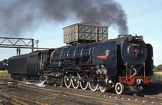
The South African Railways Class 25 4-8-4 of 1953 was a condensing steam locomotive.

<span class="mw-page-title-main">GNR Class L1</span>

The Great Northern Railway (GNR) Class L1 was a 0-8-2T side tank steam locomotive designed by Henry Ivatt. It was originally designed for suburban passenger traffic on the Metropolitan City Lines.

<span class="mw-page-title-main">South African Class KM 0-6-0+0-6-0</span>

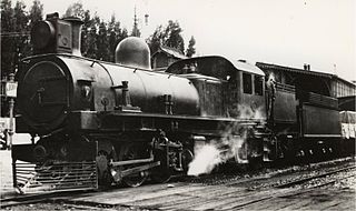
The South African Railways Class KM 0-6-0+0-6-0 of 1904 was an articulated steam locomotive from the pre-Union era in Transvaal Colony.

<span class="mw-page-title-main">Namaqualand 0-4-0WT Condenser</span>

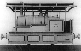
The Cape Copper Mining Company 0-4-0WT Condenser of 1886 was a South African steam locomotive from the pre-Union era in the Cape of Good Hope.

<span class="mw-page-title-main">South African type CZ tender</span>

The South African type CZ tender was a condensing steam locomotive tender.

References

  1. Titanic: Building the World's Most Famous Ship By Anton Gill, P121
  2. Roosen, Dr.-Ing. R. (17 March 1960). "Class "25" Condensing Locomotives on the South African Railways Design and Operating Experiences". J. Inst. Locomotive Engineers. 50:2 (274): 243–280. doi:10.1243/JILE_PROC_1960_050_021_02. Paper Nº607.
  3. Douglas Self (2008-04-01). "The Holcroft-Anderson Recompression Locomotive" . Retrieved 2012-02-17.
  4. 1 2 Semmens, P.W.B.; Goldfinch, A.J. (2003) [2000]. How Steam Locomotives Really Work. Oxford: Oxford University Press. p. 277. ISBN   978-0-19-860782-3.
  5. "National Museums Liverpool". Liverpoolmuseums.org.uk. Archived from the original on 2007-09-29. Retrieved 2012-02-17.
  6. Roosen 1961 , p. 244
  7. "9: Near East to Far East". The World's Railways and How They Work. Odhams. 1947. pp. 182–183.

Commons-logo.svg Media related to Condensing steam locomotives at Wikimedia Commons