Gab valve gear

Last updated
The valve gear gab of Calvert's beam engine, disengaged.
The hooked rod from the right is driven by the eccentric. When engaged, it rocks the valve arbor, the square shaft, back and forth. Bellcranks behind the shaft work the valves via the vertical pullrods. JD Varteg02.jpg
The valve gear gab of Calvert's beam engine, disengaged.
The hooked rod from the right is driven by the eccentric. When engaged, it rocks the valve arbor, the square shaft, back and forth. Bellcranks behind the shaft work the valves via the vertical pullrods.

Gab valve gear was an early form of valve gear used on steam engines. Its simplest form allowed an engine to be stopped and started. A double form, mostly used on steam locomotives, allowed easy reversing. [1]

Contents

Winding engine at Blists Hill. The red handwheel is the steam stop valve, the lever in front of the engine driver disengages the valve gear gab. Blists Hill Operating the pit winding engine.JPG
Winding engine at Blists Hill. The red handwheel is the steam stop valve, the lever in front of the engine driver disengages the valve gear gab.

Etymology

The word gab or gabb may derive from a word for mouth, recorded by the Oxford English Dictionary from 1724, and probably medieval in origin from other forms related to gossip or idle chatter. The OED also gives the steam engine sense of gab as a notch in the valvegear as possibly being of Flemish origin, from the word gabbe. This is cited in the OED from 1792. [2] The OED also cites the obviously derivative gab-lever from 1839. [3]

Origins

One of the first self-acting valve gears used for steam engines was the eccentric valve gear. This placed an eccentric on the engine's crankshaft, that in turn drove a strap and a long rod to the valve's actuating spindle. This was a simple valve gear but worked well for rotative engines that ran continuously for long periods, and in only one direction. For early mill engines this was acceptable.

Gab valve gear

The simplest form of gab valve gear or 'gab clutch' was a simple notch in the valve rod, where it hooked over the valve spindle. A hand lever allowed this notch to be lifted, thus disengaging the valve drive and promptly stopping the engine.

Stationary engines

Loose eccentric reversing gear, with a rudimentary gab Loose eccentric reversing gear (Rankin Kennedy, Modern Engines, Vol IV).jpg
Loose eccentric reversing gear, with a rudimentary gab

Where an engine had to be stopped and started precisely, such as for a winding engine, it was useful to do this by means of the valve gear. This allows the engine to be stopped within a fraction of a revolution, where using a throttle or stop valve in the steam supply slowed the engine gradually and so would be far less precise.

Winding engines for mineshafts were required to be reversed, for hoisting and lowering of the shaft cage. These engines began by using the slip-eccentric valve gear, with a gab clutch. The eccentric is loose on the crankshaft and can rotate freely between two stops. These stops represent the positions for the eccentric to run the engine in each direction. When the gab was disengaged and the crankshaft stopped, the manual lever was used to drive the engine valves in reverse, which also re-set the eccentric to the opposing position. The gab could now be re-engaged and the engine restarted in the opposing direction.

Locomotives

With the development of the first steam locomotives, reversing was an obvious necessity. Stephenson’s Locomotion used slip-eccentrics [4] although these were soon considered impractical, owing to the lack of access to the crank axles acting as both carrying axle and crankshaft. A somewhat contrived method used for the replica Locomotion is to try and display it on a track with raised ends, so that the locomotive can be allowed to roll backwards under its own weight, and re-setting its own eccentrics. [4] A better solution was to use fixed eccentrics, but to provide two of them, one for each direction. The required eccentric, and direction, was selected by engaging only one gab at a time. [5]

The first locomotive gab gears used two 'open' gabs, side by side, each potentially (when engaged) hooking over the same pin. If both gabs were ever engaged simultaneously these would jam, probably damaging the valve rod. On the footplate of a rattling locomotive with no suspension and a poor trackbed, this is known to have been the cause of breakdowns, whether by driver error or by a loose gab slipping into accidental engagement. As the gabs, unlike in the stationary engine, were remote from the driver they were provided with wide V-shaped jaws to help them engage with the pins.

X-gab gear
The upper position is in neutral, the lower positions in forward and reverse gear. Gab motion ja.png
X-gab gear
The upper position is in neutral, the lower positions in forward and reverse gear.

A better solution was to use a single double-sided gab. These were initially X-shaped and sat between the two connecting pins. [5] X-gabs were also usually reversed, so that the gab was placed on the valve spindle and the pins were instead connected to the eccentric rods. The gab now stayed still vertically and the pins were moved up and down to engage them. This was done by joining both pins with a short vertical bar. The driver's reversing lever [note 1] moved the centre of this bar, thus the pins, up and down to engage one at a time with opposite faces of the X-gab.

Another mechanism, used on Stephenson's locomotives in the 1830s, was the 'coupled gab'. [6] [7] Two open gabs were used, as for the manual open gab, although in this case they were both operated automatically by a single reversing lever. One was actuated by a bellcrank, the other through a reversing linkage from this, so that as one engaged the other was already lifted clear.

The final form of the gab valve gear was the 'closed' gab. Like the X-gab, this was a coupled pair of gabs, although in this case they faced inwards and there was a single pin between them. Once again, the gabs were driven by the eccentrics and the pin drove the valve spindle.

Developments

The use of expansive working was already recognised for stationary engines, although this was usually only required for engines working under a constant load. By shutting off the supply of steam early, the steam within the cylinder was allowed to expand whilst doing work against the piston. This provided considerable savings in efficiency of both coal and water consumption. [note 2] In 1844, William Williams, a pattern-maker for Stephenson, made the remarkable invention of realising that if a closed gab was made into a curved link, so that it fitted the pin closely throughout its travel, then the valve gear could also be set into an intermediate position, and that this would also have the effect of giving expansive working. This gear was the genesis of the well-known Stephenson link gear. [5]

Notes

    1. This was the first time that such a single lever control was used.
    2. For railway locomotives of this period, the extra range permitted by reduced water consumption was perhaps even more valuable than the coal savings.

    Related Research Articles

    <span class="mw-page-title-main">Valve gear</span> Mechanism for controlling steam flow in a reciprocating steam engine.

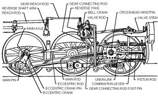
    The valve gear of a steam engine is the mechanism that operates the inlet and exhaust valves to admit steam into the cylinder and allow exhaust steam to escape, respectively, at the correct points in the cycle. It can also serve as a reversing gear. It is sometimes referred to as the "motion".

    <span class="mw-page-title-main">Steam locomotive components</span> Glossary of the main components of a typical steam locomotive

    Main components found on a typical steam locomotive include:

    <span class="mw-page-title-main">Walschaerts valve gear</span> Type of valve gear

    The Walschaerts valve gear is a type of valve gear used to regulate the flow of steam to the pistons in steam locomotives, invented by Belgian railway engineer Egide Walschaerts in 1844. The gear is sometimes named without the final "s", since it was incorrectly patented under that name. It was extensively used in steam locomotives from the late 19th century until the end of the steam era.

    <span class="mw-page-title-main">Gresley conjugated valve gear</span> Type of mechanism for controlling steam flow in a reciprocating steam engine

    The Gresley conjugated valve gear is a valve gear for steam locomotives designed by Sir Nigel Gresley, chief mechanical engineer of the LNER, assisted by Harold Holcroft. It enables a three-cylinder locomotive to operate with only the two sets of valve gear for the outside cylinders, and derives the valve motion for the inside cylinder from them by means of levers. The gear is sometimes known as the Gresley-Holcroft gear, acknowledging Holcroft's major contributions to its development.

    <span class="mw-page-title-main">Baker valve gear</span>

    After about 1910, the Baker valve gear was the main competitor to Walschaerts valve gear for steam locomotives in the United States. Strictly speaking it was not a valve gear but a variable expansion mechanism adapted to the Walschaerts layout replacing the expansion link and sliding die block. The Baker arrangement used more pivot bearings or pin joints, but avoided the die slip inherent to the expansion link, with the aim of lessening wear and the need for service; it could also facilitate longer valve travel.

    <span class="mw-page-title-main">Stephenson valve gear</span> Simple design of valve gear

    The Stephenson valve gear or Stephenson link or shifting link is a simple design of valve gear that was widely used throughout the world for various kinds of steam engines. It is named after Robert Stephenson but was invented by his employees.

    <span class="mw-page-title-main">Joy valve gear</span> Valve gear for steam engines

    Joy valve gear is a type of steam locomotive valve gear, designed by David Joy, Locomotive and Marine engineer, and patented on 8 March 1879. The British patent has not been found but the US patent has. Joy's gear is similar to Hackworth valve gear but has a compensating mechanism which corrects for "the slight inequality in the motion of the valve arising from the arc of the lever".

    <span class="mw-page-title-main">Southern valve gear</span>

    Southern valve gear was briefly popular on steam locomotives in the United States. It combines elements of the Walschaerts and Baker patterns.

    <span class="mw-page-title-main">Bulleid chain-driven valve gear</span> Steam locomotive component

    The Bulleid chain-driven valve gear is a type of steam locomotive valve gear designed by Oliver Bulleid during the Second World War for use on his Pacific (4-6-2) designs. It was peculiar to the Southern Railway in Britain, and borrowed from motor-vehicle practice in an attempt to create a compact and efficient design with a minimum of service requirements.

    <span class="mw-page-title-main">Piston valve (steam engine)</span> Form of valve within a steam engine or locomotive

    Piston valves are one form of valve used to control the flow of steam within a steam engine or locomotive. They control the admission of steam into the cylinders and its subsequent exhausting, enabling a locomotive to move under its own power. The valve consists of two piston heads on a common spindle moving inside a steam chest, which is essentially a mini-cylinder located either above or below the main cylinders of the locomotive.

    <span class="mw-page-title-main">Expansion valve (steam engine)</span>

    An expansion valve is a device in steam engine valve gear that improves engine efficiency. It operates by closing off the supply of steam early, before the piston has travelled through its full stroke. This cut-off allows the steam to then expand within the cylinder. This expanding steam is still sufficient to drive the piston, even though its pressure decreases as it expands. As less steam is supplied in the shorter time for which the valve is open, use of the expansion valve reduces the steam consumed and thus the fuel required. The engine may deliver two-thirds of the work, for only one-third of the steam.

    <span class="mw-page-title-main">Holcroft valve gear</span>

    The Holcroft valve gear was a type of conjugated valve gear designed and patented by Harold Holcroft and used on three-cylinder steam locomotives of the South Eastern & Chatham Railway (SECR). It bore many similarities to the Gresley conjugated valve gear, which it predated, as eventually used on all Gresley's three cylinder designs. It varied from the Gresley method of operation by using the combination lever assembly instead of the valve spindles to drive the middle cylinder of a three-cylinder design. This had operational advantages over Gresley's design, namely eliminating the problems of flexure, bush wear and the influence of heat in the valve spindles.

    <span class="mw-page-title-main">Oscillating cylinder steam engine</span> Steam-engine design which does not require a valve gear

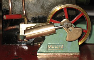
    An oscillating cylinder steam engine is a simple steam-engine design that requires no valve gear. Instead the cylinder rocks, or oscillates, as the crank moves the piston, pivoting in the mounting trunnion so that ports in the cylinder line up with ports in a fixed port face alternately to direct steam into or out of the cylinder.

    <span class="mw-page-title-main">Reversing gear</span> Controller for the valves on a steam engine

    On a steam locomotive, the reversing gear is used to control the direction of travel of the locomotive. It also adjusts the cutoff of the steam locomotive.

    <span class="mw-page-title-main">Steam motor</span>

    A steam motor is a form of steam engine used for light locomotives and light self-propelled motor cars used on railways. The origins of steam motor cars for railways go back to at least the 1850s, if not earlier, as experimental economizations for railways or railroads with marginal budgets. These first examples, at least in North America, appear to have been fitted with light reciprocating engines, and either direct or geared drives, or geared-endless chain drives. Most incorporated a passenger carrying coach attached to the engine and its boiler. Boiler types varied in these earlier examples, with vertical boilers dominant in the first decade and then with very small diameter horizontal boilers. Other examples of steam motor cars incorporated an express-baggage or luggage type car body, with coupling apparatus provided to allow the steam motor car to draw a light passenger coach.

    <span class="mw-page-title-main">Grasshopper beam engine</span> Beam engines that are pivoted at one end, rather than in the centre

    Grasshopper beam engines are beam engines that are pivoted at one end, rather than in the centre.

    <span class="mw-page-title-main">Return connecting rod engine</span>

    A return connecting rod, return piston rod or double piston rod engine or back-acting engine is a particular layout for a steam engine.

    <span class="mw-page-title-main">High-speed steam engine</span> Steam engine designed to run at comparatively high speed

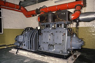
    High-speed steam engines were one of the final developments of the stationary steam engine. They ran at a high speed, of several hundred rpm, which was needed by tasks such as electricity generation.

    <span class="mw-page-title-main">Willans engine</span>

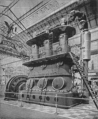
    The Willans engine or central valve engine was a high-speed stationary steam engine used mainly for electricity generation around the start of the 20th century.

    <span class="mw-page-title-main">Cornish engine valve gear</span>

    Valve gear opens and closes valves in the correct order. In rotating engines valve timings can be driven by eccentrics or cranks, but in non-rotative beam engines these options are not available. In the Cornish engine valves are driven either manually or through ‘plug rods’ and tappets driven from the beam. This permits the insertions of delays at various points in the cycle, allowing a Cornish Engine to vary from one stroke in ten minutes, to ten or more strokes in one minute, but also leads to some less familiar components when compared with rotative engines.

    References

    1. Snell, J.B. (1971). Railways: Mechanical Engineering. Longman.
    2. Specif. Kellys Patent (1792) No. 1879. 8 'Clear of the notch or gabb of the catch lever'
    3. Robinson, R.S. (1839). Nautical Steam Engineering. p. 97.
    4. 1 2 Semmens & Goldfinch (2003), p. 111.
    5. 1 2 3 Semmens, P.W.B.; Goldfinch, A.J. (2003) [2000]. How Steam Locomotives Really Work. Oxford: Oxford University Press. p. 112. ISBN   978-0-19-860782-3.
    6. Snell, J.B. (1964). Early Railways. Weidenfeld & Nicolson.
    7. Wood, Nicholas (1838). A Practical Treatise on Rail-Roads.