
A piston is a component of reciprocating engines, reciprocating pumps, gas compressors, hydraulic cylinders and pneumatic cylinders, among other similar mechanisms. It is the moving component that is contained by a cylinder and is made gas-tight by piston rings. In an engine, its purpose is to transfer force from expanding gas in the cylinder to the crankshaft via a piston rod and/or connecting rod. In a pump, the function is reversed and force is transferred from the crankshaft to the piston for the purpose of compressing or ejecting the fluid in the cylinder. In some engines, the piston also acts as a valve by covering and uncovering ports in the cylinder.

A steam engine is a heat engine that performs mechanical work using steam as its working fluid. The steam engine uses the force produced by steam pressure to push a piston back and forth inside a cylinder. This pushing force can be transformed, by a connecting rod and crank, into rotational force for work. The term "steam engine" is generally applied only to reciprocating engines as just described, not to the steam turbine. Steam engines are external combustion engines, where the working fluid is separated from the combustion products. The ideal thermodynamic cycle used to analyze this process is called the Rankine cycle. In general usage, the term steam engine can refer to either complete steam plants, such as railway steam locomotives and portable engines, or may refer to the piston or turbine machinery alone, as in the beam engine and stationary steam engine.
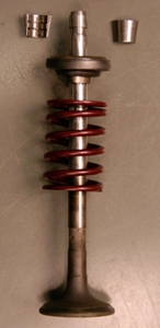
A poppet valve is a valve typically used to control the timing and quantity of gas or vapor flow into an engine.

The valve gear of a steam engine is the mechanism that operates the inlet and exhaust valves to admit steam into the cylinder and allow exhaust steam to escape, respectively, at the correct points in the cycle. It can also serve as a reversing gear. It is sometimes referred to as the "motion".
Steam power developed slowly over a period of several hundred years, progressing through expensive and fairly limited devices in the early 17th century, to useful pumps for mining in 1700, and then to Watt's improved steam engine designs in the late 18th century. It is these later designs, introduced just when the need for practical power was growing due to the Industrial Revolution, that truly made steam power commonplace.
A compound steam engine unit is a type of steam engine where steam is expanded in two or more stages. A typical arrangement for a compound engine is that the steam is first expanded in a high-pressure (HP) cylinder, then having given up heat and losing pressure, it exhausts directly into one or more larger-volume low-pressure (LP) cylinders. Multiple-expansion engines employ additional cylinders, of progressively lower pressure, to extract further energy from the steam.

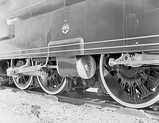
The Walschaerts valve gear is a type of valve gear invented by Belgian railway mechanical engineer Egide Walschaerts in 1844 used to regulate the flow of steam to the pistons in Steam locomotives. The gear is sometimes named without the final "s", since it was incorrectly patented under that name. It was extensively used in steam locomotives from the late 19th century until the end of the steam era.

The Caprotti valve gear is a type of steam engine valve gear invented in the early 1920s by Italian architect and engineer Arturo Caprotti. It uses camshafts and poppet valves rather than the piston valves used in other valve gear. While basing his design on automotive valves, Caprotti made several significant departures from this design to adapt the valves for steam. Having agreed a joint-venture with Worcester-based engineering company Heenan & Froude from 1938, Heenan & Froude fully acquired Caprotti post-World War II in 1947.

The Stephenson valve gear or Stephenson link or shifting link is a simple design of valve gear that was widely used throughout the world for various kinds of steam engines. It is named after Robert Stephenson but was invented by his employees.
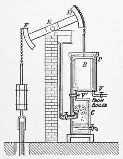
A beam engine is a type of steam engine where a pivoted overhead beam is used to apply the force from a vertical piston to a vertical connecting rod. This configuration, with the engine directly driving a pump, was first used by Thomas Newcomen around 1705 to remove water from mines in Cornwall. The efficiency of the engines was improved by engineers including James Watt, who added a separate condenser; Jonathan Hornblower and Arthur Woolf, who compounded the cylinders; and William McNaught, who devised a method of compounding an existing engine. Beam engines were first used to pump water out of mines or into canals but could be used to pump water to supplement the flow for a waterwheel powering a mill.

The slide valve is a rectilinear valve used to control the admission of steam into and emission of exhaust from the cylinder of a steam engine.
Jonathan Hornblower was an English pioneer of steam power.

Piston valves are one form of valve used to control the flow of steam within a steam engine or locomotive. They control the admission of steam into the cylinders and its subsequent exhausting, enabling a locomotive to move under its own power. The valve consists of two piston heads on a common spindle moving inside a steam chest, which is essentially a mini-cylinder located either above or below the main cylinders of the locomotive.

The first recorded rudimentary steam engine was the aeolipile mentioned by Vitruvius between 30 and 15 BC and, described by Heron of Alexandria in 1st-century Roman Egypt. Several steam-powered devices were later experimented with or proposed, such as Taqi al-Din's steam jack, a steam turbine in 16th-century Ottoman Egypt, and Thomas Savery's steam pump in 17th-century England. In 1712, Thomas Newcomen's atmospheric engine became the first commercially successful engine using the principle of the piston and cylinder, which was the fundamental type of steam engine used until the early 20th century. The steam engine was used to pump water out of coal mines.

The South African Railways Class 16E 4-6-2 of 1935 was a steam locomotive.
A duplex locomotive is a steam locomotive that divides the driving force on its wheels by using two pairs of cylinders rigidly mounted to a single locomotive frame; it is not an articulated locomotive. The concept was first used in France in 1863, but was particularly developed in the early 1930s by the Baldwin Locomotive Works, the largest commercial builder of steam locomotives in North America, under the supervision of its then chief engineer, Ralph P. Johnson.
A bash valve is a valve within a piston engine, used to control the admission of the working fluid. They are directly actuated valves, operated by contact between the piston and the valve tip.
GCR Class 9P was a design of four-cylinder steam locomotive of the 4-6-0 wheel arrangement built for hauling express passenger trains on the Great Central Railway in England. A total of six were built: one in 1917, and five in 1920. They were sometimes known as the Lord Faringdon class, from the name of the first one built.

A double chimney is a form of chimney for a steam locomotive, where the conventional single opening is duplicated, together with the blastpipe beneath it. Although the internal openings form two circles, the outside appearance is as a single elongated oval.

Valve gear opens and closes valves in the correct order. In rotating engines valve timings can be driven by eccentrics or cranks, but in non-rotative beam engines these options are not available. In the Cornish engine valves are driven either manually or through ‘plug rods’ and tappets driven from the beam. This permits the insertions of delays at various points in the cycle, allowing a Cornish Engine to vary from one stroke in ten minutes, to ten or more strokes in one minute, but also leads to some less familiar components when compared with rotative engines.
