Guy-wire

Last updated
A sailboat's mast is supported by shrouds and stays - nautical equivalents of guy wires. Schema-greement-TETE.png
A sailboat's mast is supported by shrouds and stays - nautical equivalents of guy wires.

A guy-wire, guy-line, guy-rope, down guy, or stay, also called simply a guy, is a tensioned cable designed to add stability to a freestanding structure. They are used commonly for ship masts, radio masts, wind turbines, utility poles, and tents. A thin vertical mast supported by guy wires is called a guyed mast. Structures that support antennas are frequently of a lattice construction and are called "towers". One end of the guy is attached to the structure, and the other is anchored to the ground at some distance from the mast or tower base. The tension in the diagonal guy-wire, combined with the compression and buckling strength of the structure, allows the structure to withstand lateral loads such as wind or the weight of cantilevered structures. They are installed radially, usually at equal angles about the structure, in trios and quads. As the tower leans a bit due to the wind force, the increased guy tension is resolved into a compression force in the tower or mast and a lateral force that resists the wind load. For example, antenna masts are often held up by three guy-wires at 120° angles. Structures with predictable lateral loads, such as electrical utility poles, may require only a single guy-wire to offset the lateral pull of the electrical wires, at a spot where the wires change direction.

Contents

Conductive guy cables for radio antenna masts may disturb the radiation pattern of the antenna, so their electrical characteristics must be included in the design. Usually this conductive guy cables that otherwise would consume up some of the radiation power and radiate it in some other direction than intended. To avoid this, the guy wire gets broken up into a couple of isolated sections that can not act as antennas on their own due to length differences and not being resonant at the transmission frequency.

Uses

Sailing

Guy (red arrow), controlling the spinnaker pole. Segeln Spinnaker-Achterholer.jpg
Guy (red arrow), controlling the spinnaker pole.

The guys supporting a sailboat mast are called "standing rigging" and in modern boats are stainless steel wire rope. Guys are rigged to the bow and stern, usually as a single guy. Lateral guys attach to "chain plates" port and starboard attached to the hull. Multiple guys are usually installed with spreaders to help keep the mast straight ("in column"). Temporary guys are also used on a sailboat. A fore-guy is a term for a line (rope) attached to and intended to control the free end of a spar. On a modern sloop-rigged sailboat with a symmetric spinnaker, the spinnaker pole is the spar most commonly controlled by one or more guys.

Utility pole guy-wires

Utility poles are buried in the ground and have sufficient strength to stand on their own; guys are needed on some poles only to support unbalanced lateral loads due to the utility wires attached to them, or to resist ground movement. Guys are particularly needed on dead-end (anchor) poles, where a long straight section of wire line ends, or angles off in another direction. To protect the public against faults that might allow the cable to become electrified, utility guy cables usually either have a ceramic strain insulator ("Johnny ball"), or a fiberglass guy strain insulator inserted near the top, to ensure that any dangerous voltages do not reach the lower end of the wire accessible to the public. The lower end where the cable enters the ground is often encased in a length of yellow plastic reflector to make it more visible, so that people or vehicles do not run into it.

Sidewalk guy with yellow guard, used due to the limited space between the pole and railing to the right Sidewalk guy wire.jpg
Sidewalk guy with yellow guard, used due to the limited space between the pole and railing to the right

In urban areas where the ground area around the pole is restricted, a variation called a sidewalk guy is often used. In this type the guy line extends diagonally from the top of the pole to a horizontal spar brace extending out from the middle of the pole, and from this it continues vertically to the ground. Thus, the bottom part of the guy is vertical and does not obstruct headroom, so a sidewalk can pass between the pole and the guy.

An alternative to guy-wires sometimes used on dead-end poles is a push-brace pole, a second pole set at an angle in the ground which butts diagonally against the side of the vertical pole.

Antenna mast guy-wires

Closeup of anchor end of three guy-wires used to support the KVLY-TV mast in North Dakota, the tallest guyed mast in the world. Each guy is one member of a set of three that is located radially around the tower KVLY-TV tower, North Dakota 019.jpg
Closeup of anchor end of three guy-wires used to support the KVLY-TV mast in North Dakota, the tallest guyed mast in the world. Each guy is one member of a set of three that is located radially around the tower
Guywire.jpg
Guy-wire supported mast.
KBRC antenna tower guy wires.JPG
AM antenna tower with guys attached through strain insulators at 120° angles

Electromagnetic fields from the antennas complicate the design of guys that support mast antennas. Conductive metal guy-wires whose lengths are near to quarter wavelength multiples of the transmitted frequency can distort the radiation pattern of the antenna. This also applies to guy wires of neighboring masts or metal structures situated nearby. To prevent this, each guy wire is divided by strain insulators into multiple sections, each segment non-resonant at the transmitted wavelength. Cylindrical or egg-shaped porcelain "Johnny ball" insulators (also called "egg insulators") are usually used. Non-conductive guys of Kevlar fiber (Phillystran) or extruded fiberglass rod are frequently used to not disturb the radiation pattern of the antennas. The strength and low stretch properties of Kevlar fiber approaches that of steel. However, Kevlar is very susceptible to ultraviolet degradation, so it is enclosed in a UV resistant plastic sheath.

The individual sections of conductive guys can develop large charges of static electricity, especially on very tall masts. The voltage caused by this static electricity can be several times larger than that generated by the transmitter. In order to avoid dangerous and unpredictable discharges, the insulators must be designed to withstand this high voltage, which on tall masts results in over-dimensioned backstage insulators. At each backstage insulator, a lightning arrestor in the form of an arc gap is required for the purpose of over-voltage protection in case of lightning strikes. The insulators and arrestors must be maintained carefully, because an insulator failure can result in a mast collapse. Egg insulators have the porcelain in compression and if it fails, the end loops of the guy wires are still intertwined.

Cylindrical strain insulator of type used on utility pole and antenna mast guys. Johnny ball strain insulator.JPG
Cylindrical strain insulator of type used on utility pole and antenna mast guys.

AM radio broadcast towers are often fitted with insulators at the mast base and the RF energy is fed at that point. Some are also insulated at the center for feeding the RF energy at that point. Wire rope guys are frequently used and segmented with insulators at several points. Extensive lightning protection is required for insulated towers.

On antennas for long-wave and VLF, the guys may serve an electrical function, either for capacitive lengthening of the mast or for feeding the mast with the radiation power. In these cases, the guys are fixed without an insulator on the mast, but there is at least one insulator in the guy if necessary. If guys are used for feeding the mast with high frequency power it is often possible to use a grounded mast. The power to the guys is fed via wires running from a tuning unit to the feed point on the guys.

Crane tag lines

Seabees using tag lines to steady a load during a crane lift US Navy 100308-N-1120L-014 Seabees assigned to (NMCB) 7 use tag lines to steady a 20,000-pound load during a crane lift to load cargo onto a tractor trailer.jpg
Seabees using tag lines to steady a load during a crane lift

When operating a crane, guy wires, known as tag lines, may be connected to unwieldy payloads, allowing ground crew to control rotation and swaying while maintaining a safe distance.

Firefighting

Guys can be used to raise an extension ladder in a technique called a church raise. [1]

Anchors

In ground-anchored guys, the structure which attaches the guy-wire to the ground is called an anchor . [2] The anchor must be adequate to resist the maximum tensile load of the guy wires; both the dead load of the tension of the wire and the maximum possible live load due to wind. Since the guy wire exerts its force at an angle, the anchor has both vertical and lateral (horizontal) forces on it. The anchor relies on the lateral shear strength of the soil to resist the forces from all of the guys attached to it. Several types of anchor are used:

Dead man anchors

Concrete dead man anchor for radio tower guy lines in Britain Guyed mast anchor.JPG
Concrete dead man anchor for radio tower guy lines in Britain

In this type, a hole is excavated and an object with a large surface area is placed in it with the guy wire attached, and the hole is backfilled with earth or concrete. [2] In the historical form of dead man anchor, a log is buried horizontally in a trench with the guy attached perpendicularly to its center. Modern forms are the plate anchor, in which the guy is attached to a rod with an eyelet extending from the center of a steel plate buried diagonally, perpendicular to the angle of the guy. In the concrete anchor, a diagonal rod with an eyelet extending in the guy direction is cemented into a hole filled with steel reinforced concrete. A sufficiently massive concrete block on the surface of the ground can also be used as a dead man.

Screw anchors

This type consists of a rod with wide screw blades on the end and an eyelet on the other for the guy wire. It is screwed deep into the ground, at the same angle as the guy, by a truck-mounted drill machine. These are commonly used as guy anchors for utility poles since they are quick to install with a truck mounted hydraulic powered auger drive.

Expanding anchors

A rod with a pivoted blade on the end is driven into the earth. [2] When the guy wire is attached and tensioned, its force pulls the blade open, "setting" it into the soil. These are often used by the military for rapid mast installations.

Grouted anchors

These are used in both soil and rock. [2] A hole is drilled at the angle of the guy. A steel anchor rod with an eye is inserted, and the hole around it is filled with a liquid grout consisting of concrete and an expansion agent or a structural epoxy. When the grout hardens or expands, the anchor is secure.

Guyed structures

Historically, guyed structures have been some of the tallest man-made structures in the world. There are also many structures which consist of a freestanding bottom and a guyed top. These are either partially guyed towers or additionally guyed towers, the latter of which may be used temporarily to support tall buildings during their construction.

See also

Related Research Articles

<span class="mw-page-title-main">Insulator (electricity)</span> Material that does not conduct an electric current

An electrical insulator is a material in which electric current does not flow freely. The atoms of the insulator have tightly bound electrons which cannot readily move. Other materials—semiconductors and conductors—conduct electric current more easily. The property that distinguishes an insulator is its resistivity; insulators have higher resistivity than semiconductors or conductors. The most common examples are non-metals.

<span class="mw-page-title-main">Ground (electricity)</span> Reference point in an electrical circuit from which voltages are measured

In electrical engineering, ground or earth may be a reference point in an electrical circuit from which voltages are measured, a common return path for electric current, or a direct physical connection to the Earth.

<span class="mw-page-title-main">Medium wave</span> Radio transmission using wavelengths 200-1000 m

Medium wave (MW) is a part of the medium frequency (MF) radio band used mainly for AM radio broadcasting. The spectrum provides about 120 channels with more limited sound quality than FM stations on the FM broadcast band. During the daytime, reception is usually limited to more local stations, though this is dependent on the signal conditions and quality of radio receiver used. Improved signal propagation at night allows the reception of much longer distance signals. This can cause increased interference because on most channels multiple transmitters operate simultaneously worldwide. In addition, amplitude modulation (AM) is often more prone to interference by various electronic devices, especially power supplies and computers. Strong transmitters cover larger areas than on the FM broadcast band but require more energy and longer antennas. Digital modes are possible but have not reached momentum yet.

<span class="mw-page-title-main">Whip antenna</span> Type of radio antenna

A whip antenna is an antenna consisting of a straight flexible wire or rod. The bottom end of the whip is connected to the radio receiver or transmitter. A whip antenna is a form of monopole antenna. The antenna is designed to be flexible so that it does not break easily, and the name is derived from the whip-like motion that it exhibits when disturbed. Whip antennas for portable radios are often made of a series of interlocking telescoping metal tubes, so they can be retracted when not in use. Longer whips, made for mounting on vehicles and structures, are made of a flexible fiberglass rod around a wire core and can be up to 11 m long.

<span class="mw-page-title-main">Transmission tower</span> Structure used to support an overhead power line

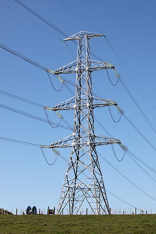
A transmission tower is a tall structure, usually a lattice tower made of steel that is used to support an overhead power line. In electrical grids, transmission towers carry high-voltage transmission lines that transport bulk electric power from generating stations to electrical substations, from which electricity is delivered to end consumers; moreover, utility poles are used to support lower-voltage sub-transmission and distribution lines that transport electricity from substations to electricity customers.

<span class="mw-page-title-main">Guyed mast</span> Tall thin vertical structure that is supported by guy lines

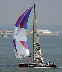
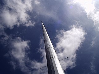
A guyed mast is a tall thin vertical structure that depends on guy lines for stability. The mast itself has the compressive strength to support its own weight, but does not have the shear strength to stand unsupported or bear loads. It requires guy lines to stay upright and to resist lateral (shear) forces such as wind loads. Examples include masts on sailing vessels, towers for telecommunications, meteorology, and masts on cranes, power shovels, draglines, and derricks, starting with the simple gin pole.

<span class="mw-page-title-main">Dead-end tower</span> Structure used in construction of overhead power lines

A dead-end tower is a fully self-supporting structure used in construction of overhead power lines. A dead-end transmission tower uses horizontal strain insulators at the end of conductors. Dead-end towers may be used at a substation as a transition to a "slack span" entering the equipment, when the circuit changes to a buried cable, when a transmission line changes direction by more than a few degrees, or at intervals along a straight run to limit the extent of a catastrophic collapse.

<span class="mw-page-title-main">Utility pole</span> Post used by public utilities to support overhead wires and related equipment

A utility pole is a column or post, usually made out of wood or aluminum alloy, used to support overhead power lines and various other public utilities, such as electrical cable, fiber optic cable, and related equipment such as transformers and street lights. It can be referred to as a transmission pole, telephone pole, telecommunication pole, power pole, hydro pole, telegraph pole, or telegraph post, depending on its application. A Stobie pole is a multi-purpose pole made of two steel joists held apart by a slab of concrete in the middle, generally found in South Australia.

<span class="mw-page-title-main">Overhead power line</span> Above-ground structure for bulk transfer and distribution of electricity

An overhead power line is a structure used in electric power transmission and distribution to transmit electrical energy along large distances. It consists of one or more conductors suspended by towers or poles. Since the surrounding air provides good cooling, insulation along long passages and allows optical inspection, overhead power lines are generally the lowest-cost method of power transmission for large quantities of electric energy.

<span class="mw-page-title-main">Blaw-Knox tower</span>

The Blaw-Knox company was an American manufacturer of steel structures and construction equipment based in Pittsburgh, Pennsylvania. The company is today best known for its radio towers, most of which were constructed during the 1930s in the United States. Although Blaw-Knox built many kinds of towers, the term Blaw-Knox tower usually refers to the company's unusual "diamond cantilever" design, which is stabilized by guy wires attached only at the vertical center of the mast, where its cross-section is widest. During the 1930s AM radio broadcasting stations adopted single mast radiator antennas, and the Blaw-Knox design was the first type used. A 1942 advertisement claims that 70% of all radio towers in the United States at the time were built by Blaw-Knox.

<span class="mw-page-title-main">Radio masts and towers</span> Tall structure designed to support antennas

Radio masts and towers are typically tall structures designed to support antennas for telecommunications and broadcasting, including television. There are two main types: guyed and self-supporting structures. They are among the tallest human-made structures. Masts are often named after the broadcasting organizations that originally built them or currently use them.

<span class="mw-page-title-main">Mast radiator</span> Type of radio frequency antenna

A mast radiator is a radio mast or tower in which the metal structure itself is energized and functions as an antenna. This design, first used widely in the 1930s, is commonly used for transmitting antennas operating at low frequencies, in the LF and MF bands, in particular those used for AM radio broadcasting stations. The conductive steel mast is electrically connected to the transmitter. Its base is usually mounted on a nonconductive support to insulate it from the ground. A mast radiator is a form of monopole antenna.

<span class="mw-page-title-main">T-antenna</span> Type of radio antenna

A ‘T’-antenna, ‘T’-aerial, or flat-top antenna is a monopole radio antenna consisting of one or more horizontal wires suspended between two supporting radio masts or buildings and insulated from them at the ends. A vertical wire is connected to the center of the horizontal wires and hangs down close to the ground, connected to the transmitter or receiver. The shape of the antenna resembles the letter "T", hence the name. The transmitter power is applied, or the receiver is connected, between the bottom of the vertical wire and a ground connection.

<span class="mw-page-title-main">Television antenna</span> Antenna used with a television to receive television programs

A television antenna is an antenna specifically designed for use with a television receiver (TV) to receive over-the-air broadcast television signals from a television station. Television reception is dependent upon the antenna as well as the transmitter. Terrestrial television is broadcast on frequencies from about 47 to 250 MHz in the very high frequency (VHF) band, and 470 to 960 MHz in the ultra high frequency (UHF) band in different countries. Television antennas are manufactured in two different types: "indoor" antennas, to be located on top of or next to the television set, and "outdoor" antennas, mounted on a mast on top of the owner's house. They can also be mounted in a loft or attic, where the dry conditions and increased elevation are advantageous for reception and antenna longevity. Outdoor antennas are more expensive and difficult to install but are necessary for adequate reception in fringe areas far from television stations. The most common types of indoor antennas are the dipole and loop antennas, and for outdoor antennas the Yagi, log periodic, and for UHF channels the multi-bay reflective array antenna.

<span class="mw-page-title-main">Monopole antenna</span> Type of radio antenna

A monopole antenna is a class of radio antenna consisting of a straight rod-shaped conductor, often mounted perpendicularly over some type of conductive surface, called a ground plane. The driving signal from the transmitter is applied, or for receiving antennas the output signal to the receiver is taken, between the lower end of the monopole and the ground plane. One side of the antenna feedline is attached to the lower end of the monopole, and the other side is attached to the ground plane, which is often the Earth. This contrasts with a dipole antenna which consists of two identical rod conductors, with the signal from the transmitter applied between the two halves of the antenna.

In RF engineering, radial has three distinct meanings, both referring to lines which radiate from a radio antenna, but neither meaning is related to the other.

<span class="mw-page-title-main">Folded unipole antenna</span> Antenna used for radio broadcasts

The folded unipole antenna is a type of monopole mast radiator antenna used as a transmitting antenna mainly in the medium wave band for AM radio broadcasting stations. It consists of a vertical metal rod or mast mounted over and connected at its base to a grounding system consisting of buried wires. The mast is surrounded by a "skirt" of vertical wires electrically attached at or near the top of the mast. The skirt wires are connected by a metal ring near the mast base, and the feedline feeding power from the transmitter is connected between the ring and the ground.

<span class="mw-page-title-main">Umbrella antenna</span>

An umbrella antenna is a capacitively top-loaded wire monopole antenna, consisting in most cases of a mast fed at the ground end, to which a number of radial wires are connected at the top, sloping downwards. One side of the feedline supplying power from the transmitter is connected to the mast, and the other side to a ground (Earthing) system of radial wires buried in the earth under the antenna. They are used as transmitting antennas below 1 MHz, in the MF, LF and particularly the VLF bands, at frequencies sufficiently low that it is impractical or infeasible to build a full size quarter-wave monopole antenna. The outer end of each radial wire, sloping down from the top of the antenna, is connected by an insulator to a supporting rope or cable anchored to the ground; the radial wires can also support the mast as guy wires. The radial wires make the antenna look like the wire frame of a giant umbrella hence the name.

<span class="mw-page-title-main">Strain insulator</span>

A strain insulator is an electrical insulator that is designed to work in mechanical tension (strain), to withstand the pull of a suspended electrical wire or cable. They are used in overhead electrical wiring, to support radio antennas and overhead power lines. A strain insulator may be inserted between two lengths of wire to isolate them electrically from each other while maintaining a mechanical connection, or where a wire attaches to a pole or tower, to transmit the pull of the wire to the support while insulating it electrically. Strain insulators were first used in telegraph systems in the mid 19th century.

In radio systems, many different antenna types are used whose properties are especially crafted for particular applications. Most often, the greatest effect is due to the size (wavelength) of the radio waves the antenna is to intercept or produce; one competing second effect is differences in optimization for receiving and for transmitting; another competing influence is the number and bandwidth of the frequenc(y/ies) that any single antenna must intercept or emit.

References

  1. Garland Fire Academy - "Church Raise". Archived from the original on 2021-12-22.
  2. 1 2 3 4 American Society of Civil Engineers, Subcommittee on Guyed Transmission Structures (1997). Design of Guyed Electrical Transmission Structures. USA: ASCE Publications. pp. 21–25. ISBN   0784402841.