Infinite impulse response (IIR) is a property applying to many linear time-invariant systems that are distinguished by having an impulse response which does not become exactly zero past a certain point, but continues indefinitely. This is in contrast to a finite impulse response (FIR) system in which the impulse response does become exactly zero at times for some finite , thus being of finite duration. Common examples of linear time-invariant systems are most electronic and digital filters. Systems with this property are known as IIR systems or IIR filters.
In practice, the impulse response, even of IIR systems, usually approaches zero and can be neglected past a certain point. However the physical systems which give rise to IIR or FIR responses are dissimilar, and therein lies the importance of the distinction. For instance, analog electronic filters composed of resistors, capacitors, and/or inductors (and perhaps linear amplifiers) are generally IIR filters. On the other hand, discrete-time filters (usually digital filters) based on a tapped delay line employing no feedback are necessarily FIR filters. The capacitors (or inductors) in the analog filter have a "memory" and their internal state never completely relaxes following an impulse (assuming the classical model of capacitors and inductors where quantum effects are ignored). But in the latter case, after an impulse has reached the end of the tapped delay line, the system has no further memory of that impulse and has returned to its initial state; its impulse response beyond that point is exactly zero.
Implementation and design
Although almost all analog electronic filters are IIR, digital filters may be either IIR or FIR. The presence of feedback in the topology of a discrete-time filter (such as the block diagram shown below) generally creates an IIR response. The z domaintransfer function of an IIR filter contains a non-trivial denominator, describing those feedback terms. The transfer function of an FIR filter, on the other hand, has only a numerator as expressed in the general form derived below. All of the coefficients with (feedback terms) are zero and the filter has no finite poles.
The transfer functions pertaining to IIR analog electronic filters have been extensively studied and optimized for their amplitude and phase characteristics. These continuous-time filter functions are described in the Laplace domain. Desired solutions can be transferred to the case of discrete-time filters whose transfer functions are expressed in the z domain, through the use of certain mathematical techniques such as the bilinear transform, impulse invariance, or pole–zero matching method. Thus digital IIR filters can be based on well-known solutions for analog filters such as the Chebyshev filter, Butterworth filter, and elliptic filter, inheriting the characteristics of those solutions.
Transfer function derivation
Digital filters are often described and implemented in terms of the difference equation that defines how the output signal is related to the input signal:
where:
is the feedforward filter order
are the feedforward filter coefficients
is the feedback filter order
are the feedback filter coefficients
is the input signal
is the output signal.
A more condensed form of the difference equation is:
which, when rearranged, becomes:
To find the transfer function of the filter, we first take the Z-transform of each side of the above equation, where we use the time-shift property to obtain:
We define the transfer function to be:
Considering that in most IIR filter designs coefficient is 1, the IIR filter transfer function takes the more traditional form:
An example of a block diagram of an IIR filter. The block is a unit delay.
Stability
The transfer function allows one to judge whether or not a system is bounded-input, bounded-output (BIBO) stable. To be specific, the BIBO stability criterion requires that the ROC of the system includes the unit circle. For example, for a causal system, all poles of the transfer function have to have an absolute value smaller than one. In other words, all poles must be located within a unit circle in the -plane.
The poles are defined as the values of which make the denominator of equal to 0:
Clearly, if then the poles are not located at the origin of the -plane. This is in contrast to the FIR filter where all poles are located at the origin, and is therefore always stable.
IIR filters are sometimes preferred over FIR filters because an IIR filter can achieve a much sharper transition region roll-off than an FIR filter of the same order.
governed by the parameter , a real number with . is stable and causal with a pole at . The time-domain impulse response can be shown to be given by:
where is the unit step function. It can be seen that is non-zero for all , thus an impulse response which continues infinitely.
IIR filter example
Advantages and disadvantages
The main advantage digital IIR filters have over FIR filters is their efficiency in implementation, in order to meet a specification in terms of passband, stopband, ripple, and/or roll-off. Such a set of specifications can be accomplished with a lower order (Q in the above formulae) IIR filter than would be required for an FIR filter meeting the same requirements. If implemented in a signal processor, this implies a correspondingly fewer number of calculations per time step; the computational savings is often of a rather large factor.
On the other hand, FIR filters can be easier to design, for instance, to match a particular frequency response requirement. This is particularly true when the requirement is not one of the usual cases (high-pass, low-pass, notch, etc.) which have been studied and optimized for analog filters. Also FIR filters can be easily made to be linear phase (constant group delay vs frequency)—a property that is not easily met using IIR filters and then only as an approximation (for instance with the Bessel filter). Another issue regarding digital IIR filters is the potential for limit cycle behavior when idle, due to the feedback system in conjunction with quantization.
Design Methods
Impulse Invariance
Impulse invariance is a technique for designing discrete-time infinite-impulse-response (IIR) filters from continuous-time filters in which the impulse response of the continuous-time system is sampled to produce the impulse response of the discrete-time system. Impulse invariance is one of the commonly used methods to meet the two basic requirements of the mapping from the s-plane to the z-plane. This is obtained by solving the T(z) that has the same output value at the same sampling time as the analog filter, and it is only applicable when the inputs are in a pulse. Note that all inputs of the digital filter generated by this method are approximate values, except for pulse inputs that are very accurate. This is the simplest IIR filter design method. It is the most accurate at low frequencies, so it is usually used in low-pass filters.
For Laplace transform or z-transform, the output after the transformation is just the input multiplied by the corresponding transformation function, T(s) or T(z). Y(s) and Y(z) are the converted output of input X(s) and input X(z), respectively.
When applying the Laplace transform or z-transform on the unit impulse, the result is 1. Hence, the output results after the conversion are
Now the output of the analog filter is just the inverse Laplace transform in the time domain.
If we use nT instead of t, we can get the output y(nT) derived from the pulse at the sampling time. It can also be expressed as y(n)
This discrete time signal can be applied z-transform to get T(z)
The last equation mathematically describes that a digital IIR filter is to perform z-transform on the analog signal that has been sampled and converted to T(s) by Laplace, which is usually simplified to
Pay attention to the fact that there is a multiplier T appearing in the formula. This is because even if the Laplace transform and z-transform for the unit pulse are 1, the pulse itself is not necessarily the same. For analog signals, the pulse has an infinite value but the area is 1 at t=0, but it is 1 at the discrete-time pulse t=0, so the existence of a multiplier T is required.
Step Invariance
Step invariance is a better design method than impulse invariant. The digital filter has several segments of input with different constants when sampling, which is composed of discrete steps. The step invariant IIR filter is less accurate than the same input step signal to the ADC. However, it is a better approximation for any input than the impulse invariant. Step invariant solves the problem of the same sample values when T(z) and T(s) are both step inputs. The input to the digital filter is u(n), and the input to the analog filter is u(t). Apply z-transform and Laplace transform on these two inputs to obtain the converted output signal. Perform z-transform on step input Converted output after z-transform Perform Laplace transform on step input Converted output after Laplace transform The output of the analog filter is y(t), which is the inverse Laplace transform of Y(s). If sampled every T seconds, it is y(n), which is the inverse conversion of Y(z).These signals are used to solve for the digital filter and the analog filter and have the same output at the sampling time. The following equation points out the solution of T(z), which is the approximate formula for the analog filter.
Bilinear Transform
The bilinear transform is a special case of a conformal mapping, often used to convert a transfer function of a linear, time-invariant (LTI) filter in the continuous-time domain (often called an analog filter) to a transfer function of a linear, shift-invariant filter in the discrete-time domain. The bilinear transform is a first-order approximation of the natural logarithm function that is an exact mapping of the z-plane to the s-plane. When the Laplace transform is performed on a discrete-time signal (with each element of the discrete-time sequence attached to a correspondingly delayed unit impulse), the result is precisely the Z transform of the discrete-time sequence with the substitution of
where is the numerical integration step size of the trapezoidal rule used in the bilinear transform derivation; or, in other words, the sampling period. The above bilinear approximation can be solved for or a similar approximation for can be performed.
The inverse of this mapping (and its first-order bilinear approximation) is
This relationship is used in the Laplace transfer function of any analog filter or the digital infinite impulse response (IIR) filter T(z) of the analog filter. The bilinear transform essentially uses this first order approximation and substitutes into the continuous-time transfer function,
That is
which is used to calculate the IIR digital filter, starting from the Laplace transfer function of the analog filter.
The bilinear transform is used in digital signal processing and discrete-time control theory to transform continuous-time system representations to discrete-time and vice versa.
In mathematics, convolution is a mathematical operation on two functions that produces a third function that expresses how the shape of one is modified by the other. The term convolution refers to both the result function and to the process of computing it. It is defined as the integral of the product of the two functions after one is reversed and shifted. The integral is evaluated for all values of shift, producing the convolution function.
Linear filters process time-varying input signals to produce output signals, subject to the constraint of linearity. In most cases these linear filters are also time invariant in which case they can be analyzed exactly using LTI system theory revealing their transfer functions in the frequency domain and their impulse responses in the time domain. Real-time implementations of such linear signal processing filters in the time domain are inevitably causal, an additional constraint on their transfer functions. An analog electronic circuit consisting only of linear components will necessarily fall in this category, as will comparable mechanical systems or digital signal processing systems containing only linear elements. Since linear time-invariant filters can be completely characterized by their response to sinusoids of different frequencies, they are sometimes known as frequency filters.
In engineering, a transfer function of a system, sub-system, or component is a mathematical function which theoretically models the system's output for each possible input. They are widely used in electronics and control systems. In some simple cases, this function is a two-dimensional graph of an independent scalar input versus the dependent scalar output, called a transfer curve or characteristic curve. Transfer functions for components are used to design and analyze systems assembled from components, particularly using the block diagram technique, in electronics and control theory.
In signal processing, a digital filter is a system that performs mathematical operations on a sampled, discrete-time signal to reduce or enhance certain aspects of that signal. This is in contrast to the other major type of electronic filter, the analog filter, which is typically an electronic circuit operating on continuous-time analog signals.
A low-pass filter is a filter that passes signals with a frequency lower than a selected cutoff frequency and attenuates signals with frequencies higher than the cutoff frequency. The exact frequency response of the filter depends on the filter design. The filter is sometimes called a high-cut filter, or treble-cut filter in audio applications. A low-pass filter is the complement of a high-pass filter.
In mathematics and signal processing, the Z-transform converts a discrete-time signal, which is a sequence of real or complex numbers, into a complex frequency-domain representation.
Filter design is the process of designing a signal processing filter that satisfies a set of requirements, some of which may be conflicting. The purpose is to find a realization of the filter that meets each of the requirements to a sufficient degree to make it useful.
Analog signal processing is a type of signal processing conducted on continuous analog signals by some analog means. "Analog" indicates something that is mathematically represented as a set of continuous values. This differs from "digital" which uses a series of discrete quantities to represent signal. Analog values are typically represented as a voltage, electric current, or electric charge around components in the electronic devices. An error or noise affecting such physical quantities will result in a corresponding error in the signals represented by such physical quantities.
In signal processing, a finite impulse response (FIR) filter is a filter whose impulse response is of finite duration, because it settles to zero in finite time. This is in contrast to infinite impulse response (IIR) filters, which may have internal feedback and may continue to respond indefinitely.
Digital control is a branch of control theory that uses digital computers to act as system controllers. Depending on the requirements, a digital control system can take the form of a microcontroller to an ASIC to a standard desktop computer. Since a digital computer is a discrete system, the Laplace transform is replaced with the Z-transform. Since a digital computer has finite precision, extra care is needed to ensure the error in coefficients, analog-to-digital conversion, digital-to-analog conversion, etc. are not producing undesired or unplanned effects.
In signal processing, specifically control theory, bounded-input, bounded-output (BIBO) stability is a form of stability for signals and systems that take inputs. If a system is BIBO stable, then the output will be bounded for every input to the system that is bounded.
In system analysis, among other fields of study, a linear time-invariant system is a system that produces an output signal from any input signal subject to the constraints of linearity and time-invariance; these terms are briefly defined below. These properties apply to many important physical systems, in which case the response y(t) of the system to an arbitrary input x(t) can be found directly using convolution: y(t) = x(t) ∗ h(t) where h(t) is called the system's impulse response and ∗ represents convolution. What's more, there are systematic methods for solving any such system, whereas systems not meeting both properties are generally more difficult to solve analytically. A good example of an LTI system is any electrical circuit consisting of resistors, capacitors, inductors and linear amplifiers.
The Goertzel algorithm is a technique in digital signal processing (DSP) for efficient evaluation of the individual terms of the discrete Fourier transform (DFT). It is useful in certain practical applications, such as recognition of dual-tone multi-frequency signaling (DTMF) tones produced by the push buttons of the keypad of a traditional analog telephone. The algorithm was first described by Gerald Goertzel in 1958.
The zero-order hold (ZOH) is a mathematical model of the practical signal reconstruction done by a conventional digital-to-analog converter (DAC). That is, it describes the effect of converting a discrete-time signal to a continuous-time signal by holding each sample value for one sample interval. It has several applications in electrical communication.
First-order hold (FOH) is a mathematical model of the practical reconstruction of sampled signals that could be done by a conventional digital-to-analog converter (DAC) and an analog circuit called an integrator. For FOH, the signal is reconstructed as a piecewise linear approximation to the original signal that was sampled. A mathematical model such as FOH is necessary because, in the sampling and reconstruction theorem, a sequence of Dirac impulses, xs(t), representing the discrete samples, x(nT), is low-pass filtered to recover the original signal that was sampled, x(t). However, outputting a sequence of Dirac impulses is impractical. Devices can be implemented, using a conventional DAC and some linear analog circuitry, to reconstruct the piecewise linear output for either predictive or delayed FOH.
Impulse invariance is a technique for designing discrete-time infinite-impulse-response (IIR) filters from continuous-time filters in which the impulse response of the continuous-time system is sampled to produce the impulse response of the discrete-time system. The frequency response of the discrete-time system will be a sum of shifted copies of the frequency response of the continuous-time system; if the continuous-time system is approximately band-limited to a frequency less than the Nyquist frequency of the sampling, then the frequency response of the discrete-time system will be approximately equal to it for frequencies below the Nyquist frequency.
In signal processing, a filter is a device or process that removes some unwanted components or features from a signal. Filtering is a class of signal processing, the defining feature of filters being the complete or partial suppression of some aspect of the signal. Most often, this means removing some frequencies or frequency bands. However, filters do not exclusively act in the frequency domain; especially in the field of image processing many other targets for filtering exist. Correlations can be removed for certain frequency components and not for others without having to act in the frequency domain. Filters are widely used in electronics and telecommunication, in radio, television, audio recording, radar, control systems, music synthesis, image processing, and computer graphics.
Two dimensional filters have seen substantial development effort due to their importance and high applicability across several domains. In the 2-D case the situation is quite different from the 1-D case, because the multi-dimensional polynomials cannot in general be factored. This means that an arbitrary transfer function cannot generally be manipulated into a form required by a particular implementation. The input-output relationship of a 2-D IIR filter obeys a constant-coefficient linear partial difference equation from which the value of an output sample can be computed using the input samples and previously computed output samples. Because the values of the output samples are fed back, the 2-D filter, like its 1-D counterpart, can be unstable.
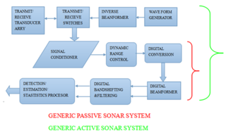
Sonar systems are generally used underwater for range finding and detection. Active sonar emits an acoustic signal, or pulse of sound, into the water. The sound bounces off the target object and returns an “echo” to the sonar transducer. Unlike active sonar, passive sonar does not emit its own signal, which is an advantage for military vessels. But passive sonar cannot measure the range of an object unless it is used in conjunction with other passive listening devices. Multiple passive sonar devices must be used for triangulation of a sound source. No matter whether active sonar or passive sonar, the information included in the reflected signal can not be used without technical signal processing. To extract the useful information from the mixed signal, some steps are taken to transfer the raw acoustic data.
This page is based on this Wikipedia article Text is available under the CC BY-SA 4.0 license; additional terms may apply. Images, videos and audio are available under their respective licenses.