Linear filters process time-varying input signals to produce output signals, subject to the constraint of linearity. In most cases these linear filters are also time invariant in which case they can be analyzed exactly using LTI system theory revealing their transfer functions in the frequency domain and their impulse responses in the time domain. Real-time implementations of such linear signal processing filters in the time domain are inevitably causal, an additional constraint on their transfer functions. An analog electronic circuit consisting only of linear components will necessarily fall in this category, as will comparable mechanical systems or digital signal processing systems containing only linear elements. Since linear time-invariant filters can be completely characterized by their response to sinusoids of different frequencies, they are sometimes known as frequency filters.
In engineering, a transfer function of a system, sub-system, or component is a mathematical function that models the system's output for each possible input. They are widely used in electronic engineering tools like circuit simulators and control systems. In some simple cases, this function can be represented as two-dimensional graph of an independent scalar input versus the dependent scalar output, called a transfer curve or characteristic curve. Transfer functions for components are used to design and analyze systems assembled from components, particularly using the block diagram technique, in electronics and control theory.

In signal processing, a digital filter is a system that performs mathematical operations on a sampled, discrete-time signal to reduce or enhance certain aspects of that signal. This is in contrast to the other major type of electronic filter, the analog filter, which is typically an electronic circuit operating on continuous-time analog signals.
In signal processing, group delay and phase delay are two related ways of describing how a signal's frequency components are delayed in time when passing through a linear time-invariant (LTI) system. Phase delay describes the time shift of a sinusoidal component. Group delay describes the time shift of the envelope of a wave packet, a "pack" or "group" of oscillations centered around one frequency that travel together, formed for instance by multiplying a sine wave by an envelope.
A low-pass filter is a filter that passes signals with a frequency lower than a selected cutoff frequency and attenuates signals with frequencies higher than the cutoff frequency. The exact frequency response of the filter depends on the filter design. The filter is sometimes called a high-cut filter, or treble-cut filter in audio applications. A low-pass filter is the complement of a high-pass filter.
In signal processing and electronics, the frequency response of a system is the quantitative measure of the magnitude and phase of the output as a function of input frequency. The frequency response is widely used in the design and analysis of systems, such as audio and control systems, where they simplify mathematical analysis by converting governing differential equations into algebraic equations. In an audio system, it may be used to minimize audible distortion by designing components so that the overall response is as flat (uniform) as possible across the system's bandwidth. In control systems, such as a vehicle's cruise control, it may be used to assess system stability, often through the use of Bode plots. Systems with a specific frequency response can be designed using analog and digital filters.
Analog signal processing is a type of signal processing conducted on continuous analog signals by some analog means. "Analog" indicates something that is mathematically represented as a set of continuous values. This differs from "digital" which uses a series of discrete quantities to represent signal. Analog values are typically represented as a voltage, electric current, or electric charge around components in the electronic devices. An error or noise affecting such physical quantities will result in a corresponding error in the signals represented by such physical quantities.
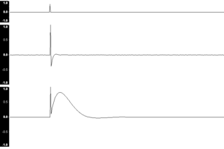
In signal processing and control theory, the impulse response, or impulse response function (IRF), of a dynamic system is its output when presented with a brief input signal, called an impulse (δ(t)). More generally, an impulse response is the reaction of any dynamic system in response to some external change. In both cases, the impulse response describes the reaction of the system as a function of time (or possibly as a function of some other independent variable that parameterizes the dynamic behavior of the system).
In control theory and signal processing, a linear, time-invariant system is said to be minimum-phase if the system and its inverse are causal and stable.
In control theory, a causal system is a system where the output depends on past and current inputs but not future inputs—i.e., the output depends only on the input for values of .
Infinite impulse response (IIR) is a property applying to many linear time-invariant systems that are distinguished by having an impulse response which does not become exactly zero past a certain point, but continues indefinitely. This is in contrast to a finite impulse response (FIR) system in which the impulse response does become exactly zero at times for some finite , thus being of finite duration. Common examples of linear time-invariant systems are most electronic and digital filters. Systems with this property are known as IIR systems or IIR filters.
In systems theory, a linear system is a mathematical model of a system based on the use of a linear operator. Linear systems typically exhibit features and properties that are much simpler than the nonlinear case. As a mathematical abstraction or idealization, linear systems find important applications in automatic control theory, signal processing, and telecommunications. For example, the propagation medium for wireless communication systems can often be modeled by linear systems.
In signal processing, specifically control theory, bounded-input, bounded-output (BIBO) stability is a form of stability for signals and systems that take inputs. If a system is BIBO stable, then the output will be bounded for every input to the system that is bounded.
A time-variant system is a system whose output response depends on moment of observation as well as moment of input signal application. In other words, a time delay or time advance of input not only shifts the output signal in time but also changes other parameters and behavior. Time variant systems respond differently to the same input at different times. The opposite is true for time invariant systems (TIV).

In system analysis, among other fields of study, a linear time-invariant (LTI) system is a system that produces an output signal from any input signal subject to the constraints of linearity and time-invariance; these terms are briefly defined below. These properties apply (exactly or approximately) to many important physical systems, in which case the response y(t) of the system to an arbitrary input x(t) can be found directly using convolution: y(t) = (x ∗ h)(t) where h(t) is called the system's impulse response and ∗ represents convolution (not to be confused with multiplication). What's more, there are systematic methods for solving any such system (determining h(t)), whereas systems not meeting both properties are generally more difficult (or impossible) to solve analytically. A good example of an LTI system is any electrical circuit consisting of resistors, capacitors, inductors and linear amplifiers.

In signal processing, a causal filter is a linear and time-invariant causal system. The word causal indicates that the filter output depends only on past and present inputs. A filter whose output also depends on future inputs is non-causal, whereas a filter whose output depends only on future inputs is anti-causal. Systems that are realizable must be causal because such systems cannot act on a future input. In effect that means the output sample that best represents the input at time comes out slightly later. A common design practice for digital filters is to create a realizable filter by shortening and/or time-shifting a non-causal impulse response. If shortening is necessary, it is often accomplished as the product of the impulse-response with a window function.
The zero-order hold (ZOH) is a mathematical model of the practical signal reconstruction done by a conventional digital-to-analog converter (DAC). That is, it describes the effect of converting a discrete-time signal to a continuous-time signal by holding each sample value for one sample interval. It has several applications in electrical communication.
First-order hold (FOH) is a mathematical model of the practical reconstruction of sampled signals that could be done by a conventional digital-to-analog converter (DAC) and an analog circuit called an integrator. For FOH, the signal is reconstructed as a piecewise linear approximation to the original signal that was sampled. A mathematical model such as FOH (or, more commonly, the zero-order hold) is necessary because, in the sampling and reconstruction theorem, a sequence of Dirac impulses, xs(t), representing the discrete samples, x(nT), is low-pass filtered to recover the original signal that was sampled, x(t). However, outputting a sequence of Dirac impulses is impractical. Devices can be implemented, using a conventional DAC and some linear analog circuitry, to reconstruct the piecewise linear output for either predictive or delayed FOH.
A shift invariant system is the discrete equivalent of a time-invariant system, defined such that if is the response of the system to , then is the response of the system to . That is, in a shift-invariant system the contemporaneous response of the output variable to a given value of the input variable does not depend on when the input occurs; time shifts are irrelevant in this regard.
In signal processing, a filter is a device or process that removes some unwanted components or features from a signal. Filtering is a class of signal processing, the defining feature of filters being the complete or partial suppression of some aspect of the signal. Most often, this means removing some frequencies or frequency bands. However, filters do not exclusively act in the frequency domain; especially in the field of image processing many other targets for filtering exist. Correlations can be removed for certain frequency components and not for others without having to act in the frequency domain. Filters are widely used in electronics and telecommunication, in radio, television, audio recording, radar, control systems, music synthesis, image processing, computer graphics, and structural dynamics.