
Bandwidth is the difference between the upper and lower frequencies in a continuous band of frequencies. It is typically measured in hertz, and depending on context, may specifically refer to passband bandwidth or baseband bandwidth. Passband bandwidth is the difference between the upper and lower cutoff frequencies of, for example, a band-pass filter, a communication channel, or a signal spectrum. Baseband bandwidth applies to a low-pass filter or baseband signal; the bandwidth is equal to its upper cutoff frequency.
The decibel is a relative unit of measurement equal to one tenth of a bel (B). It expresses the ratio of two values of a power or root-power quantity on a logarithmic scale. Two signals whose levels differ by one decibel have a power ratio of 101/10 or root-power ratio of 101⁄20.

The neper is a logarithmic unit for ratios of measurements of physical field and power quantities, such as gain and loss of electronic signals. The unit's name is derived from the name of John Napier, the inventor of logarithms. As is the case for the decibel and bel, the neper is a unit defined in the international standard ISO 80000. It is not part of the International System of Units (SI), but is accepted for use alongside the SI.
In telecommunications, return loss is a measure in relative terms of the power of the signal reflected by a discontinuity in a transmission line or optical fiber. This discontinuity can be caused by a mismatch between the termination or load connected to the line and the characteristic impedance of the line. It is usually expressed as a ratio in decibels (dB);
Signal-to-noise ratio is a measure used in science and engineering that compares the level of a desired signal to the level of background noise. SNR is defined as the ratio of signal power to noise power, often expressed in decibels. A ratio higher than 1:1 indicates more signal than noise.

In electronics, gain is a measure of the ability of a two-port circuit to increase the power or amplitude of a signal from the input to the output port by adding energy converted from some power supply to the signal. It is usually defined as the mean ratio of the signal amplitude or power at the output port to the amplitude or power at the input port. It is often expressed using the logarithmic decibel (dB) units. A gain greater than one, that is, amplification, is the defining property of an active component or circuit, while a passive circuit will have a gain of less than one.
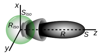
In electromagnetics, an antenna's gain is a key performance parameter which combines the antenna's directivity and radiation efficiency. The term power gain has been deprecated by IEEE. In a transmitting antenna, the gain describes how well the antenna converts input power into radio waves headed in a specified direction. In a receiving antenna, the gain describes how well the antenna converts radio waves arriving from a specified direction into electrical power. When no direction is specified, gain is understood to refer to the peak value of the gain, the gain in the direction of the antenna's main lobe. A plot of the gain as a function of direction is called the antenna pattern or radiation pattern. It is not to be confused with directivity, which does not take an antenna's radiation efficiency into account.
Sound intensity, also known as acoustic intensity, is defined as the power carried by sound waves per unit area in a direction perpendicular to that area. The SI unit of intensity, which includes sound intensity, is the watt per square meter (W/m2). One application is the noise measurement of sound intensity in the air at a listener's location as a sound energy quantity.
Sound power or acoustic power is the rate at which sound energy is emitted, reflected, transmitted or received, per unit time. It is defined as "through a surface, the product of the sound pressure, and the component of the particle velocity, at a point on the surface in the direction normal to the surface, integrated over that surface." The SI unit of sound power is the watt (W). It relates to the power of the sound force on a surface enclosing a sound source, in air. For a sound source, unlike sound pressure, sound power is neither room-dependent nor distance-dependent. Sound pressure is a property of the field at a point in space, while sound power is a property of a sound source, equal to the total power emitted by that source in all directions. Sound power passing through an area is sometimes called sound flux or acoustic flux through that area.
In telecommunications, particularly in radio frequency engineering, signal strength refers to the transmitter power output as received by a reference antenna at a distance from the transmitting antenna. High-powered transmissions, such as those used in broadcasting, are expressed in dB-millivolts per metre (dBmV/m). For very low-power systems, such as mobile phones, signal strength is usually expressed in dB-microvolts per metre (dBμV/m) or in decibels above a reference level of one milliwatt (dBm). In broadcasting terminology, 1 mV/m is 1000 μV/m or 60 dBμ.
In electronics, the common mode rejection ratio (CMRR) of a differential amplifier is a metric used to quantify the ability of the device to reject common-mode signals, i.e. those that appear simultaneously and in-phase on both inputs. An ideal differential amplifier would have infinite CMRR, however this is not achievable in practice. A high CMRR is required when a differential signal must be amplified in the presence of a possibly large common-mode input, such as strong electromagnetic interference (EMI). An example is audio transmission over balanced line in sound reinforcement or recording.
Scattering parameters or S-parameters describe the electrical behavior of linear electrical networks when undergoing various steady state stimuli by electrical signals.
dBc is the power ratio of a signal to a carrier signal, expressed in decibels. For example, phase noise is expressed in dBc/Hz at a given frequency offset from the carrier. dBc can also be used as a measurement of Spurious-Free Dynamic Range (SFDR) between the desired signal and unwanted spurious outputs resulting from the use of signal converters such as a digital-to-analog converter or a frequency mixer.
In telecommunications, the carrier-to-noise ratio, often written CNR or C/N, is the signal-to-noise ratio (SNR) of a modulated signal. The term is used to distinguish the CNR of the radio frequency passband signal from the SNR of an analog base band message signal after demodulation. For example, with FM radio, the strength of the 100 MHz carrier with modulations would be considered for CNR, whereas the audio frequency analogue message signal would be for SNR; in each case, compared to the apparent noise. If this distinction is not necessary, the term SNR is often used instead of CNR, with the same definition.

An attenuator is an electronic device that reduces the power of a signal without appreciably distorting its waveform.
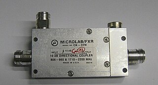
Power dividers and directional couplers are passive devices used mostly in the field of radio technology. They couple a defined amount of the electromagnetic power in a transmission line to a port enabling the signal to be used in another circuit. An essential feature of directional couplers is that they only couple power flowing in one direction. Power entering the output port is coupled to the isolated port but not to the coupled port. A directional coupler designed to split power equally between two ports is called a hybrid coupler.

The Π pad is a specific type of attenuator circuit in electronics whereby the topology of the circuit is formed in the shape of the Greek capital letter pi (Π).
Mismatch loss in transmission line theory is the amount of power expressed in decibels that will not be available on the output due to impedance mismatches and signal reflections. A transmission line that is properly terminated, that is, terminated with the same impedance as that of the characteristic impedance of the transmission line, will have no reflections and therefore no mismatch loss. Mismatch loss represents the amount of power wasted in the system. It can also be thought of as the amount of power gained if the system was perfectly matched. Impedance matching is an important part of RF system design; however, in practice there will likely be some degree of mismatch loss. In real systems, relatively little loss is due to mismatch loss and is often on the order of 1dB.
Roll-off is the steepness of a transfer function with frequency, particularly in electrical network analysis, and most especially in connection with filter circuits in the transition between a passband and a stopband. It is most typically applied to the insertion loss of the network, but can, in principle, be applied to any relevant function of frequency, and any technology, not just electronics. It is usual to measure roll-off as a function of logarithmic frequency; consequently, the units of roll-off are either decibels per decade (dB/decade), where a decade is a tenfold increase in frequency, or decibels per octave (dB/8ve), where an octave is a twofold increase in frequency.

The T pad is a specific type of attenuator circuit in electronics whereby the topology of the circuit is formed in the shape of the letter "T".


