Instant centre of rotation

Last updated
Sketch 1: Instantaneous center P of a moving plane Mechanism analysis.png
Sketch 1: Instantaneous center P of a moving plane

The instant center of rotation (also known as instantaneous velocity center, [1] instantaneous center, or pole of planar displacement) of a body undergoing planar movement is a point that has zero velocity at a particular instant of time. At this instant, the velocity vectors of the other points in the body generate a circular field around this center of rotation which is identical to what is generated by a pure rotation.

Contents

Planar movement of a body is often described using a plane figure moving in a two-dimensional plane. The instant center is the point in the moving plane around which all other points are rotating at a specific instant of time.

The continuous movement of a plane has an instant center for every value of the time parameter. This generates a curve called the moving centrode. The points in the fixed plane corresponding to these instant centers form the fixed centrode.

The generalization of this concept to 3-dimensional space is that of a twist around a screw. The screw has an axis which is a line in 3D space (not necessarily through the origin), the axis of rotation; the screw also has a finite pitch (a fixed translation along its axis corresponding to a rotation about the screw axis).

Pole of a planar displacement

Sketch 2: Pole of a planar displacement Pole-object-A1-A2.png
Sketch 2: Pole of a planar displacement

The instant center can be considered the limiting case of the pole of a planar displacement.

The planar displacement of a body from position 1 to position 2 is defined by the combination of a planar rotation and planar translation. For any planar displacement there is a point in the moving body that is in the same place before and after the displacement. The displacement can be viewed as a rotation around this pole.

Construction for the pole of a planar displacement: First, select two points A and B in the moving body and locate the corresponding points in the two positions; see the illustration. Construct the perpendicular bisectors to the two segments A1A2 and B1B2. The intersection P of these two bisectors is the pole of the planar displacement. Notice that A1 and A2 lie on a circle around P. This is true for the corresponding positions of every point in the body.

If the two positions of a body are separated by an instant of time in a planar movement, then the pole of a displacement becomes the instant center. In this case, the segments constructed between the instantaneous positions of the points A and B become the velocity vectors VA and VB. The lines perpendicular to these velocity vectors intersect in the instant center.

The algebraic construction of the Cartesian coordinates can be arranged as follows: The midpoint between and has the Cartesian coordinates

and the midpoint between and has the Cartesian coordinates

The two angles from to and from to measured counter-clockwise relative to the horizontal are determined by

Find the position of

Method 1:

Taking the correct branches of the tangent. Let the center of the rotation have distances and to the two midpoints. Assuming clockwise rotation (otherwise switch the sign of ):

Rewrite this as a 4 × 4 inhomogeneous system of linear equations with 4 unknowns (the two distances and the two coordinates of the center):

The coordinates of the center of the rotation are the first two components of the solution vector

Method 2:

Find equations of the bisectors of two segments A1A2 and B1B2 as follows

The equation of a straight line in point- slope form is: where is the point and is the slope.

The equation of the bisector of A1A2 is

The equation of the bisector of B1B2 is

These two bisectors intersect at so a system of 2 equations with 2 unknowns and coefficients can be written

The solution of this system is

Pure translation

If the displacement between two positions is a pure translation, then the perpendicular bisectors of the segments A1B1 and A2B2 form parallel lines. These lines are considered to intersect at a point on the line at infinity, thus the pole of this planar displacement is said to "lie at infinity" in the direction of the perpendicular bisectors.

In the limit, pure translation becomes planar movement with point velocity vectors that are parallel. In this case, the instant center is said to lie at infinity in the direction perpendicular to the velocity vectors.

Instant center of a wheel rolling without slipping

Sketch 3: Rolling wheel. Wheelrotation.png
Sketch 3: Rolling wheel.
Instant centre of rotation of a rolling wheel broken down into points. By breaking down the rolling wheel into several points, it can be more easily seen how all points of the wheel rotate around a single point at each instant. This point is the instant centre of rotation, shown in black. Instant centre of rotation of a rolling wheel broken down into points (smaller image size).gif
Instant centre of rotation of a rolling wheel broken down into points. By breaking down the rolling wheel into several points, it can be more easily seen how all points of the wheel rotate around a single point at each instant. This point is the instant centre of rotation, shown in black.

Consider the planar movement of a circular wheel rolling without slipping on a linear road; see sketch 3. The wheel rotates around its axis M, which translates in a direction parallel to the road. The point of contact P of the wheel with road does not slip, which means the point P has zero velocity with respect to the road. Thus, at the instant the point P on the wheel comes in contact with the road it becomes an instant center.

The set of points of the moving wheel that become instant centers is the circle itself, which defines the moving centrode. The points in the fixed plane that correspond to these instant centers is the line of the road, which defines the fixed centrode.

The velocity vector of a point A in the wheel is perpendicular to the segment AP and is proportional to the length of this segment. In particular, the velocities of points in the wheel are determined by the angular velocity of the wheel in rotation around P. The velocity vectors of a number of points are illustrated in sketch 3 and can be calculated using the following equation:

where is velocity of point A, angular velocity of wheel and vector from point P to A.

The further a point in the wheel is from the instant center P, the proportionally larger its speed. Therefore, the point at the top of the wheel moves in the same direction as the center M of the wheel, but twice as fast, since it is twice the distance away from P. All points that are a distance equal to the radius of the wheel 'r' from point P move at the same speed as the point M but in different directions. This is shown for a point on the wheel that has the same speed as M but moves in the direction tangent to the circle around P.

Relative center of rotation for two contacting planar bodies

Sketch 4: Example relative center of rotation. Two bodies in contact at C, one rotating about A and the other about B must have a relative center of rotation somewhere along the line AB. Since the parts cannot interpenetrate the relative rotation center must also be along the normal direction to the contact and through C. The only possible solution is if the relative center is at D. RelativeCenterOfRotation.png
Sketch 4: Example relative center of rotation. Two bodies in contact at C, one rotating about A and the other about B must have a relative center of rotation somewhere along the line AB. Since the parts cannot interpenetrate the relative rotation center must also be along the normal direction to the contact and through C. The only possible solution is if the relative center is at D.

If two planar rigid bodies are in contact, and each body has its own distinct center of rotation, then the relative center of rotation between the bodies has to lie somewhere on the line connecting the two centers. As a result, since pure rolling can only exist when the center of rotation is at the point of contact (as seen above with the wheel on the road), it is only when the point of contact goes through the line connecting the two rotation centers that pure rolling can be achieved. This is known in involute gear design as the pitch point, where there is no relative sliding between the gears. In fact, the gearing ratio between the two rotating parts is found by the ratio of the two distances to the relative center. In the example in Sketch 4 the gearing ratio is

Instant center of rotation and mechanisms

Sketch 1 above shows a four-bar linkage where a number of instant centers of rotation are illustrated. The rigid body noted by the letters BAC is connected with links P1-A and P2-B to a base or frame.

The three moving parts of this mechanism (the base is not moving) are: link P1-A, link P2-B, and body BAC. For each of these three parts an instant center of rotation may be determined.

Considering first link P1-A: all points on this link, including point A, rotate around point P1. Since P1 is the only point not moving in the given plane it may be called the instant center of rotation for this link. Point A, at distance P1-A from P1, moves in a circular motion in a direction perpendicular to the link P1-A, as indicated by vector VA.

The same applies to link P2-B: point P2 is the instant center of rotation for this link and point B moves in the direction as indicated by vector VB.

For determining the instant center of rotation of the third element of the linkage, the body BAC, the two points A and B are used because its moving characteristics are known, as derived from the information about the links P1-A and P2-B.

The direction of speed of point A is indicated by vector VA. Its instant center of rotation must be perpendicular to this vector (as VA is tangentially located on the circumference of a circle). The only line that fills the requirement is a line colinear with link P1-A. Somewhere on this line there is a point P, the instant center of rotation for the body BAC.

What applies to point A also applies to point B, therefore this instant center of rotation P is located on a line perpendicular to vector VB, a line colinear with link P2-B. Therefore, the instant center of rotation P of body BAC is the point where the lines through P1-A and P2-B cross.

Since this instant center of rotation P is the center for all points on the body BAC for any random point, say point C, the speed and direction of movement may be determined: connect P to C. The direction of movement of point C is perpendicular to this connection. The speed is proportional to the distance to point P.

Continuing this approach with the two links P1-A and P2-B rotating around their own instant centers of rotation the centrode for instant center of rotation P may be determined. From this the path of movement for C or any other point on body BAC may be determined.

Examples of application

In biomechanical research the instant center of rotation is observed for the functioning of the joints in the upper and lower extremities. [2] For example, in analysing the knee, [3] [4] [5] ankle, [6] or shoulder joints. [7] [8] Such knowledge assists in developing artificial joints and prosthesis, such as elbow [9] or finger joints. [10]

Study of the joints of horses: "...velocity vectors determined from the instant centers of rotation indicated that the joint surfaces slide on each other." [11]

Studies on turning a vessel moving through water. [12]

The braking characteristics of a car may be improved by varying the design of a brake pedal mechanism. [13]

Designing the suspension of a bicycle, [14] or of a car. [15]

In the case of the coupler link in a four-bar linkage, such as a double wishbone suspension in front view, the perpendiculars to the velocity lie along the links joining the grounded link to the coupler link. This construction is used to establish the kinematic roll center of the suspension.

See also

Related Research Articles

<span class="mw-page-title-main">Pauli matrices</span> Matrices important in quantum mechanics and the study of spin

In mathematical physics and mathematics, the Pauli matrices are a set of three 2 × 2 complex matrices which are Hermitian, involutory and unitary. Usually indicated by the Greek letter sigma, they are occasionally denoted by tau when used in connection with isospin symmetries.

In electrodynamics, elliptical polarization is the polarization of electromagnetic radiation such that the tip of the electric field vector describes an ellipse in any fixed plane intersecting, and normal to, the direction of propagation. An elliptically polarized wave may be resolved into two linearly polarized waves in phase quadrature, with their polarization planes at right angles to each other. Since the electric field can rotate clockwise or counterclockwise as it propagates, elliptically polarized waves exhibit chirality.

Kinematics is a subfield of physics, developed in classical mechanics, that describes the motion of points, bodies (objects), and systems of bodies without considering the forces that cause them to move. Kinematics, as a field of study, is often referred to as the "geometry of motion" and is occasionally seen as a branch of mathematics. A kinematics problem begins by describing the geometry of the system and declaring the initial conditions of any known values of position, velocity and/or acceleration of points within the system. Then, using arguments from geometry, the position, velocity and acceleration of any unknown parts of the system can be determined. The study of how forces act on bodies falls within kinetics, not kinematics. For further details, see analytical dynamics.

<span class="mw-page-title-main">Angular velocity</span> Pseudovector representing an objects change in orientation with respect to time

In physics, angular velocity, also known as angular frequency vector, is a pseudovector representation of how the angular position or orientation of an object changes with time, i.e. how quickly an object rotates around an axis of rotation and how fast the axis itself changes direction.

<span class="mw-page-title-main">Hyperboloid</span> Unbounded quadric surface

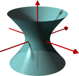
In geometry, a hyperboloid of revolution, sometimes called a circular hyperboloid, is the surface generated by rotating a hyperbola around one of its principal axes. A hyperboloid is the surface obtained from a hyperboloid of revolution by deforming it by means of directional scalings, or more generally, of an affine transformation.

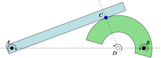
In mechanics and geometry, the 3D rotation group, often denoted SO(3), is the group of all rotations about the origin of three-dimensional Euclidean space under the operation of composition.

Unit quaternions, known as versors, provide a convenient mathematical notation for representing spatial orientations and rotations of elements in three dimensional space. Specifically, they encode information about an axis-angle rotation about an arbitrary axis. Rotation and orientation quaternions have applications in computer graphics, computer vision, robotics, navigation, molecular dynamics, flight dynamics, orbital mechanics of satellites, and crystallographic texture analysis.

<span class="mw-page-title-main">Four-vector</span> 4-dimensional vector in relativity

In special relativity, a four-vector is an object with four components, which transform in a specific way under Lorentz transformations. Specifically, a four-vector is an element of a four-dimensional vector space considered as a representation space of the standard representation of the Lorentz group, the representation. It differs from a Euclidean vector in how its magnitude is determined. The transformations that preserve this magnitude are the Lorentz transformations, which include spatial rotations and boosts.

<span class="mw-page-title-main">Proper time</span> Elapsed time between two events as measured by a clock that passes through both events

In relativity, proper time along a timelike world line is defined as the time as measured by a clock following that line. The proper time interval between two events on a world line is the change in proper time, which is independent of coordinates, and is a Lorentz scalar. The interval is the quantity of interest, since proper time itself is fixed only up to an arbitrary additive constant, namely the setting of the clock at some event along the world line.

<span class="mw-page-title-main">Projectile motion</span> Motion of launched objects due to gravity

Projectile motion is a form of motion experienced by an object or particle that is projected in a gravitational field, such as from Earth's surface, and moves along a curved path under the action of gravity only. In the particular case of projectile motion on Earth, most calculations assume the effects of air resistance are passive and negligible. The curved path of objects in projectile motion was shown by Galileo to be a parabola, but may also be a straight line in the special case when it is thrown directly upward or downward. The study of such motions is called ballistics, and such a trajectory is a ballistic trajectory. The only force of mathematical significance that is actively exerted on the object is gravity, which acts downward, thus imparting to the object a downward acceleration towards the Earth’s center of mass. Because of the object's inertia, no external force is needed to maintain the horizontal velocity component of the object's motion. Taking other forces into account, such as aerodynamic drag or internal propulsion, requires additional analysis. A ballistic missile is a missile only guided during the relatively brief initial powered phase of flight, and whose remaining course is governed by the laws of classical mechanics.

<span class="mw-page-title-main">Euler's rotation theorem</span> Movement with a fixed point is rotation

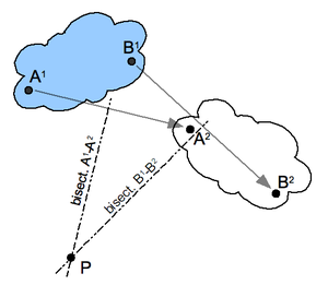
In geometry, Euler's rotation theorem states that, in three-dimensional space, any displacement of a rigid body such that a point on the rigid body remains fixed, is equivalent to a single rotation about some axis that runs through the fixed point. It also means that the composition of two rotations is also a rotation. Therefore the set of rotations has a group structure, known as a rotation group.

In rotordynamics, the rigid rotor is a mechanical model of rotating systems. An arbitrary rigid rotor is a 3-dimensional rigid object, such as a top. To orient such an object in space requires three angles, known as Euler angles. A special rigid rotor is the linear rotor requiring only two angles to describe, for example of a diatomic molecule. More general molecules are 3-dimensional, such as water, ammonia, or methane.

<span class="mw-page-title-main">Osculating circle</span> Circle of immediate corresponding curvature of a curve at a point

An osculating circle is a circle that best approximates the curvature of a curve at a specific point. It is tangent to the curve at that point and has the same curvature as the curve at that point. The osculating circle provides a way to understand the local behavior of a curve and is commonly used in differential geometry and calculus.

In physics, the algebra of physical space (APS) is the use of the Clifford or geometric algebra Cl3,0(R) of the three-dimensional Euclidean space as a model for (3+1)-dimensional spacetime, representing a point in spacetime via a paravector.

<span class="mw-page-title-main">Ekman layer</span> Force equilibrium layer in a liquid

The Ekman layer is the layer in a fluid where there is a force balance between pressure gradient force, Coriolis force and turbulent drag. It was first described by Vagn Walfrid Ekman. Ekman layers occur both in the atmosphere and in the ocean.

<span class="mw-page-title-main">Toroidal coordinates</span>

Toroidal coordinates are a three-dimensional orthogonal coordinate system that results from rotating the two-dimensional bipolar coordinate system about the axis that separates its two foci. Thus, the two foci and in bipolar coordinates become a ring of radius in the plane of the toroidal coordinate system; the -axis is the axis of rotation. The focal ring is also known as the reference circle.

<span class="mw-page-title-main">Oblate spheroidal coordinates</span> Three-dimensional orthogonal coordinate system

Oblate spheroidal coordinates are a three-dimensional orthogonal coordinate system that results from rotating the two-dimensional elliptic coordinate system about the non-focal axis of the ellipse, i.e., the symmetry axis that separates the foci. Thus, the two foci are transformed into a ring of radius in the x-y plane. Oblate spheroidal coordinates can also be considered as a limiting case of ellipsoidal coordinates in which the two largest semi-axes are equal in length.

In classical mechanics, the Udwadia–Kalaba formulation is a method for deriving the equations of motion of a constrained mechanical system. The method was first described by Vereshchagin for the particular case of robotic arms, and later generalized to all mechanical systems by Firdaus E. Udwadia and Robert E. Kalaba in 1992. The approach is based on Gauss's principle of least constraint. The Udwadia–Kalaba method applies to both holonomic constraints and nonholonomic constraints, as long as they are linear with respect to the accelerations. The method generalizes to constraint forces that do not obey D'Alembert's principle.

In classical mechanics, the central-force problem is to determine the motion of a particle in a single central potential field. A central force is a force that points from the particle directly towards a fixed point in space, the center, and whose magnitude only depends on the distance of the object to the center. In a few important cases, the problem can be solved analytically, i.e., in terms of well-studied functions such as trigonometric functions.

A proper reference frame in the theory of relativity is a particular form of accelerated reference frame, that is, a reference frame in which an accelerated observer can be considered as being at rest. It can describe phenomena in curved spacetime, as well as in "flat" Minkowski spacetime in which the spacetime curvature caused by the energy–momentum tensor can be disregarded. Since this article considers only flat spacetime—and uses the definition that special relativity is the theory of flat spacetime while general relativity is a theory of gravitation in terms of curved spacetime—it is consequently concerned with accelerated frames in special relativity.

References

  1. Illustrated Dictionary of Mechanical Engineering: English, German, French, Dutch, Russian (Springer Science & Business Media, 17 Apr. 2013 - 422 pages)
  2. "Muscle Physiology — Joint Moment Arm".
  3. Knee joint motion description and measurement [ permanent dead link ]
  4. Moorehead JD, Montgomery SC, Harvey DM (Sep 2003). "Instant center of rotation estimation using the Reuleaux technique and a Lateral Extrapolation technique". J Biomech. 36 (9): 1301–7. doi:10.1016/S0021-9290(03)00156-8. PMID   12893038.
  5. Hollman JH, Deusinger RH, Van Dillen LR, Matava MJ (Aug 2003). "Gender differences in surface rolling and gliding kinematics of the knee". Clin Orthop Relat Res. 413 (413): 208–21. doi:10.1097/01.blo.0000072902.36018.fe. PMID   12897612. S2CID   45191914.
  6. Maganaris CN, Baltzopoulos V, Sargeant AJ (Aug 1998). "Changes in Achilles tendon moment arm from rest to maximum isometric plantarflexion: in vivo observations in man". Journal of Physiology. 510 (Pt 3): 977–85. doi:10.1111/j.1469-7793.1998.977bj.x. PMC   2231068 . PMID   9660906. Archived from the original on 2012-09-08.
  7. Biomechanics of shoulder
  8. Poppen NK, Walker PS (Mar 1976). "Normal and abnormal motion of the shoulder". J Bone Joint Surg Am. 58 (2): 195–201. doi:10.2106/00004623-197658020-00006. PMID   1254624.
  9. US 5030237 Elbow prosthesis
  10. "Pyrocarbon Finger Joint Implant" (PDF). Archived from the original (PDF) on 2011-07-21. Retrieved 2008-08-22.
  11. Colahan P, Piotrowski G, Poulos P (Sep 1988). "Kinematic analysis of the instant centers of rotation of the equine metacarpophalangeal joint". Am J Vet Res. 49 (9): 1560–5. PMID   3223666.
  12. "PART VI Vessel Navigation and Manoeuvering" (PDF). Archived from the original (PDF) on 2009-12-15. Retrieved 2008-08-22.
  13. GB 1443270 Variable Mechanical Ratio Brake Pedal Mounts - General Motors, 1976
  14. US 7100930 Bicycle rear suspension system
  15. Reza N. Jazar (2008). Vehicle Dynamics: Theory and Application. Berlin: Springer. ISBN   978-0-387-74243-4.