Light field

Last updated

A light field, or lightfield, is a vector function that describes the amount of light flowing in every direction through every point in a space. The space of all possible light rays is given by the five-dimensional plenoptic function, and the magnitude of each ray is given by its radiance. Michael Faraday was the first to propose that light should be interpreted as a field, much like the magnetic fields on which he had been working. [1] The term light field was coined by Andrey Gershun in a classic 1936 paper on the radiometric properties of light in three-dimensional space.

Contents

The term "radiance field" may also be used to refer to similar, or identical [2] concepts. The term is used in modern research such as neural radiance fields

The plenoptic function

Radiance L along a ray can be thought of as the amount of light traveling along all possible straight lines through a tube whose size is determined by its solid angle and cross-sectional area. Plenoptic-function-a.png
Radiance L along a ray can be thought of as the amount of light traveling along all possible straight lines through a tube whose size is determined by its solid angle and cross-sectional area.

For geometric optics—i.e., to incoherent light and to objects larger than the wavelength of light—the fundamental carrier of light is a ray. The measure for the amount of light traveling along a ray is radiance, denoted by L and measured in W·sr−1·m−2, i.e., watts (W) per steradian (sr) per meter squared (m2). The steradian is a measure of solid angle, and meters squared are used as a measure of cross-sectional area, as shown at right.

Parameterizing a ray in 3D space by position (x, y, z) and direction (th, ph). Plenoptic function b.svg
Parameterizing a ray in 3D space by position (x, y, z) and direction (θ, ϕ).

The radiance along all such rays in a region of three-dimensional space illuminated by an unchanging arrangement of lights is called the plenoptic function. [3] The plenoptic illumination function is an idealized function used in computer vision and computer graphics to express the image of a scene from any possible viewing position at any viewing angle at any point in time. It is not used in practice computationally, but is conceptually useful in understanding other concepts in vision and graphics. [4] Since rays in space can be parameterized by three coordinates, x, y, and z and two angles θ and ϕ, as shown at left, it is a five-dimensional function, that is, a function over a five-dimensional manifold equivalent to the product of 3D Euclidean space and the 2-sphere.

Summing the irradiance vectors D1 and D2 arising from two light sources I1 and I2 produces a resultant vector D having the magnitude and direction shown. Gershun-light-field-fig17.png
Summing the irradiance vectors D1 and D2 arising from two light sources I1 and I2 produces a resultant vector D having the magnitude and direction shown.

The light field at each point in space can be treated as an infinite collection of vectors, one per direction impinging on the point, with lengths proportional to their radiances.

Integrating these vectors over any collection of lights, or over the entire sphere of directions, produces a single scalar value—the total irradiance at that point, and a resultant direction. The figure shows this calculation for the case of two light sources. In computer graphics, this vector-valued function of 3D space is called the vector irradiance field. [6] The vector direction at each point in the field can be interpreted as the orientation of a flat surface placed at that point to most brightly illuminate it.

Higher dimensionality

Time, wavelength, and polarization angle can be treated as additional dimensions, yielding higher-dimensional functions, accordingly.

The 4D light field

Radiance along a ray remains constant if there are no blockers. Plenoptic-function-c.png
Radiance along a ray remains constant if there are no blockers.

In a plenoptic function, if the region of interest contains a concave object (e.g., a cupped hand), then light leaving one point on the object may travel only a short distance before another point on the object blocks it. No practical device could measure the function in such a region.

However, for locations outside the object's convex hull (e.g., shrink-wrap), the plenoptic function can be measured by capturing multiple images. In this case the function contains redundant information, because the radiance along a ray remains constant throughout its length. The redundant information is exactly one dimension, leaving a four-dimensional function variously termed the photic field, the 4D light field [7] or lumigraph. [8] Formally, the field is defined as radiance along rays in empty space.

The set of rays in a light field can be parameterized in a variety of ways. The most common is the two-plane parameterization. While this parameterization cannot represent all rays, for example rays parallel to the two planes if the planes are parallel to each other, it relates closely to the analytic geometry of perspective imaging. A simple way to think about a two-plane light field is as a collection of perspective images of the st plane (and any objects that may lie astride or beyond it), each taken from an observer position on the uv plane. A light field parameterized this way is sometimes called a light slab.

Some alternative parameterizations of the 4D light field, which represents the flow of light through an empty region of three-dimensional space. Left: points on a plane or curved surface and directions leaving each point. Center: pairs of points on the surface of a sphere. Right: pairs of points on two planes in general (meaning any) position. Light-field-parameterizations.png
Some alternative parameterizations of the 4D light field, which represents the flow of light through an empty region of three-dimensional space. Left: points on a plane or curved surface and directions leaving each point. Center: pairs of points on the surface of a sphere. Right: pairs of points on two planes in general (meaning any) position.

Sound analog

The analog of the 4D light field for sound is the sound field or wave field, as in wave field synthesis, and the corresponding parametrization is the Kirchhoff–Helmholtz integral, which states that, in the absence of obstacles, a sound field over time is given by the pressure on a plane. Thus this is two dimensions of information at any point in time, and over time, a 3D field.

This two-dimensionality, compared with the apparent four-dimensionality of light, is because light travels in rays (0D at a point in time, 1D over time), while by the Huygens–Fresnel principle, a sound wave front can be modeled as spherical waves (2D at a point in time, 3D over time): light moves in a single direction (2D of information), while sound expands in every direction. However, light travelling in non-vacuous media may scatter in a similar fashion, and the irreversibility or information lost in the scattering is discernible in the apparent loss of a system dimension.

Image refocusing

Because light field provides spatial and angular information, we can alter the position of focal planes after exposure, which is often termed refocusing. The principle of refocusing is to obtain conventional 2-D photographs from a light field through the integral transform. The transform takes a lightfield as its input and generates a photograph focused on a specific plane.

Assuming represents a 4-D light field that records light rays traveling from position on the first plane to position on the second plane, where is the distance between two planes, a 2-D photograph at any depth can be obtained from the following integral transform: [9]

,

or more concisely,

,

where , , and is the photography operator.

In practice, this formula cannot be directly used because a plenoptic camera usually captures discrete samples of the lightfield , and hence resampling (or interpolation) is needed to compute . Another problem is high computation complexity. To compute an 2-D photograph from an 4-D light field, the complexity of the formula is . [9]

Fourier slice photography

One way to reduce the complexity of computation is to adopt the concept of Fourier slice theorem: [9] The photography operator can be viewed as a shear followed by projection. The result should be proportional to a dilated 2-D slice of the 4-D Fourier transform of a light field. More precisely, a refocused image can be generated from the 4-D Fourier spectrum of a light field by extracting a 2-D slice, applying an inverse 2-D transform, and scaling. The asymptotic complexity of the algorithm is .

Discrete focal stack transform

Another way to efficiently compute 2-D photographs is to adopt discrete focal stack transform (DFST). [10] DFST is designed to generate a collection of refocused 2-D photographs, or so-called Focal Stack. This method can be implemeted by fast fractional fourier transform (FrFT).

The discrete photography operator is defined as follows for a lightfield sampled in a 4-D grid , :

Because is usually not on the 4-D grid, DFST adopts trigonometric interpolation to compute the non-grid values.

The algorithm consists of these steps:

Methods to create light fields

In computer graphics, light fields are typically produced either by rendering a 3D model or by photographing a real scene. In either case, to produce a light field, views must be obtained for a large collection of viewpoints. Depending on the parameterization, this collection typically spans some portion of a line, circle, plane, sphere, or other shape, although unstructured collections are possible. [11]

Devices for capturing light fields photographically may include a moving handheld camera or a robotically controlled camera, [12] an arc of cameras (as in the bullet time effect used in The Matrix ), a dense array of cameras, [13] handheld cameras, [14] [15] microscopes, [16] or other optical system. [17]

The number of images in a light field depends on the application. A light field capture of Michelangelo's statue of Night [18] contains 24,000 1.3-megapixel images, which is considered large as of 2022. For light field rendering to completely capture an opaque object, images must be taken of at least the front and back. Less obviously, for an object that lies astride the st plane, finely spaced images must be taken on the uv plane (in the two-plane parameterization shown above).

The number and arrangement of images in a light field, and the resolution of each image, are together called the "sampling" of the 4D light field. [19] Also of interest are the effects of occlusion, [20] lighting and reflection. [21]

Applications

A downward-facing light source (F-F') induces a light field whose irradiance vectors curve outwards. Using calculus, Gershun could compute the irradiance falling on points (P1, P2) on a surface. ) Gershun-light-field-fig24.png
A downward-facing light source (F-F') induces a light field whose irradiance vectors curve outwards. Using calculus, Gershun could compute the irradiance falling on points (P1, P2) on a surface. )

Illumination engineering

Gershun's reason for studying the light field was to derive (in closed form) illumination patterns that would be observed on surfaces due to light sources of various shapes positioned above these surface. [23] The branch of optics devoted to illumination engineering is nonimaging optics. [24] It extensively uses the concept of flow lines (Gershun's flux lines) and vector flux (Gershun's light vector). However, the light field (in this case the positions and directions defining the light rays) is commonly described in terms of phase space and Hamiltonian optics.

Light field rendering

Extracting appropriate 2D slices from the 4D light field of a scene, enables novel views of the scene. [25] Depending on the parameterization of the light field and slices, these views might be perspective, orthographic, crossed-slit, [26] general linear cameras, [27] multi-perspective, [28] or another type of projection. Light field rendering is one form of image-based rendering.

Synthetic aperture photography

Integrating an appropriate 4D subset of the samples in a light field can approximate the view that would be captured by a camera having a finite (i.e., non-pinhole) aperture. Such a view has a finite depth of field. Shearing or warping the light field before performing this integration can focus on different fronto-parallel [29] or oblique [30] planes. Images captured by digital cameras that capture the light field [14] can be refocused.

3D display

Presenting a light field using technology that maps each sample to the appropriate ray in physical space produces an autostereoscopic visual effect akin to viewing the original scene. Non-digital technologies for doing this include integral photography, parallax panoramagrams, and holography; digital technologies include placing an array of lenslets over a high-resolution display screen, or projecting the imagery onto an array of lenslets using an array of video projectors. An array of video cameras can capture and display a time-varying light field. This essentially constitutes a 3D television system. [31] Modern approaches to light-field display explore co-designs of optical elements and compressive computation to achieve higher resolutions, increased contrast, wider fields of view, and other benefits. [32]

Brain imaging

Neural activity can be recorded optically by genetically encoding neurons with reversible fluorescent markers such as GCaMP that indicate the presence of calcium ions in real time. Since light field microscopy captures full volume information in a single frame, it is possible to monitor neural activity in individual neurons randomly distributed in a large volume at video framerate. [33] Quantitative measurement of neural activity can be done despite optical aberrations in brain tissue and without reconstructing a volume image, [34] and be used to monitor activity in thousands of neurons. [35]

Generalized Scene Reconstruction (GSR)

This is a method of 3D reconstruction from multiple images that creates a scene model comprising a generalized light field and a relightable matter field. [36] The generalized light field represents light flowing in every direction through every point in the field. The relightable matter field represents the light interaction properties and emissivity of matter occupying every point in the field. Scene data structures can be implemented using Neural Networks, [37] [38] [39] and Physics-based structures, [40] [41] among others. [36] The light and matter fields are at least partially disentangled. [36] [42]

Holographic stereograms

Image generation and predistortion of synthetic imagery for holographic stereograms is one of the earliest examples of computed light fields. [43]

Glare reduction

Glare arises due to multiple scattering of light inside the camera body and lens optics that reduces image contrast. While glare has been analyzed in 2D image space, [44] it is useful to identify it as a 4D ray-space phenomenon. [45] Statistically analyzing the ray-space inside a camera allows the classification and removal of glare artifacts. In ray-space, glare behaves as high frequency noise and can be reduced by outlier rejection. Such analysis can be performed by capturing the light field inside the camera, but it results in the loss of spatial resolution. Uniform and non-uniform ray sampling can be used to reduce glare without significantly compromising image resolution. [45]

See also

Notes

  1. Faraday, Michael (30 April 2009). "LIV. Thoughts on ray-vibrations". Philosophical Magazine. Series 3. 28 (188): 345–350. doi:10.1080/14786444608645431. Archived from the original on 2013-02-18.
  2. https://arxiv.org/pdf/2003.08934.pdf
  3. Adelson 1991
  4. Wong 2002
  5. Gershun, fig 17
  6. Arvo, 1994
  7. Levoy 1996
  8. Gortler 1996
  9. 1 2 3 Ng, Ren (2005). "Fourier slice photography". ACM SIGGRAPH 2005 Papers. New York, New York, USA: ACM Press. pp. 735–744. doi:10.1145/1186822.1073256. ISBN   9781450378253. S2CID   1806641.
  10. Nava, F. Pérez; Marichal-Hernández, J.G.; Rodríguez-Ramos, J.M. (August 2008). "The Discrete Focal Stack Transform". 2008 16th European Signal Processing Conference: 1–5.
  11. Buehler 2001
  12. Levoy 2002
  13. Kanade 1998; Yang 2002; Wilburn 2005
  14. 1 2 Ng 2005
  15. Georgiev 2006; Marwah 2013
  16. Levoy 2006
  17. Bolles 1987
  18. "A light field of Michelangelo's statue of Night". accademia.stanford.edu. Retrieved 2022-02-08.
  19. Chai (2000)
  20. Durand (2005)
  21. Ramamoorthi (2006)
  22. Gershun, fig 24
  23. Ashdown 1993
  24. Chaves 2015; Winston 2005
  25. Levoy 1996; Gortler 1996
  26. Zomet 2003
  27. Yu and McMillan 2004
  28. Rademacher 1998
  29. Isaksen 2000
  30. Vaish 2005
  31. Javidi 2002; Matusik 2004
  32. Wetzstein 2012, 2011; Lanman 2011, 2010
  33. Grosenick, 2009, 2017; Perez, 2015
  34. Pegard, 2016
  35. Grosenick, 2017
  36. 1 2 3 Leffingwell, 2018
  37. Mildenhall, 2020
  38. Rudnev, Viktor; Elgharib, Mohamed; Smith, William; Liu, Lingjie; Golyanik, Vladislav; Theobalt, Christian (21 Jul 2022). "NeRF for Outdoor Scene Relighting". European Conference on Computer Vision (ECCV) 2022: 1–22. arXiv: 2112.05140 .
  39. Srinivasan, Pratual; Deng, Boyang; Zhang, Xiuming; Tancik, Matthew; Mildenhall, Ben; Barron, Jonathan (7 Dec 2020). "NeRV: Neural Reflectance and Visibility Fields for Relighting and View Synthesis". CVPR: 1–12. arXiv: 2012.03927 .
  40. Yu & Fridovich-Keil, 2021
  41. Kerbl, Bernhard; Kopanas, Georgios; Leimkühler, Thomas; Drettakis, George (2023-08-08). "3D Gaussian Splatting for Real-Time Radiance Field Rendering". arXiv: 2308.04079 [cs.GR].
  42. Zhang, Jingyang; Yao, Yao; Li, Shiwei; Liu, Jingbo; Fang, Tian; McKinnon, David; Tsin, Yanghai; Quan, Long (30 Mar 2023). "NeILF++: Inter-Reflectable Light Fields for Geometry and Material Estimation". pp. 1–5. arXiv: 2303.17147 [cs.CV].
  43. Halle 1991, 1994
  44. Talvala 2007
  45. 1 2 Raskar 2008

Related Research Articles

<span class="mw-page-title-main">Rendering (computer graphics)</span> Process of generating an image from a model

Rendering or image synthesis is the process of generating a photorealistic or non-photorealistic image from a 2D or 3D model by means of a computer program. The resulting image is referred to as the render. Multiple models can be defined in a scene file containing objects in a strictly defined language or data structure. The scene file contains geometry, viewpoint, textures, lighting, and shading information describing the virtual scene. The data contained in the scene file is then passed to a rendering program to be processed and output to a digital image or raster graphics image file. The term "rendering" is analogous to the concept of an artist's impression of a scene. The term "rendering" is also used to describe the process of calculating effects in a video editing program to produce the final video output.

In mechanics and geometry, the 3D rotation group, often denoted SO(3), is the group of all rotations about the origin of three-dimensional Euclidean space under the operation of composition.

A Bézier triangle is a special type of Bézier surface that is created by interpolation of control points.

A directional derivative is a concept in multivariable calculus that measures the rate at which a function changes in a particular direction at a given point.

<span class="mw-page-title-main">Volume rendering</span> Representing a 3D-modeled object or dataset as a 2D projection

In scientific visualization and computer graphics, volume rendering is a set of techniques used to display a 2D projection of a 3D discretely sampled data set, typically a 3D scalar field.

<span class="mw-page-title-main">Chiral model</span> Model of mesons in the massless quark limit

In nuclear physics, the chiral model, introduced by Feza Gürsey in 1960, is a phenomenological model describing effective interactions of mesons in the chiral limit (where the masses of the quarks go to zero), but without necessarily mentioning quarks at all. It is a nonlinear sigma model with the principal homogeneous space of a Lie group as its target manifold. When the model was originally introduced, this Lie group was the SU(N), where N is the number of quark flavors. The Riemannian metric of the target manifold is given by a positive constant multiplied by the Killing form acting upon the Maurer–Cartan form of SU(N).

The computer graphics pipeline, also known as the rendering pipeline or graphics pipeline, is a framework within computer graphics that outlines the necessary procedures for transforming a three-dimensional (3D) scene into a two-dimensional (2D) representation on a screen. Once a 3D model is generated, the graphics pipeline converts the model into a visually perceivable format on the computer display. Due to the dependence on specific software, hardware configurations, and desired display attributes, a universally applicable graphics pipeline does not exist. Nevertheless, graphics application programming interfaces (APIs), such as Direct3D, OpenGL and Vulkan were developed to standardize common procedures and oversee the graphics pipeline of a given hardware accelerator. These APIs provide an abstraction layer over the underlying hardware, relieving programmers from the need to write code explicitly targeting various graphics hardware accelerators like AMD, Intel, Nvidia, and others.

In differential geometry, the four-gradient is the four-vector analogue of the gradient from vector calculus.

<span class="mw-page-title-main">Specular highlight</span> Bright spot of light that appears on shiny objects when illuminated

A specular highlight is the bright spot of light that appears on shiny objects when illuminated. Specular highlights are important in 3D computer graphics, as they provide a strong visual cue for the shape of an object and its location with respect to light sources in the scene.

<span class="mw-page-title-main">Geometry processing</span>

Geometry processing is an area of research that uses concepts from applied mathematics, computer science and engineering to design efficient algorithms for the acquisition, reconstruction, analysis, manipulation, simulation and transmission of complex 3D models. As the name implies, many of the concepts, data structures, and algorithms are directly analogous to signal processing and image processing. For example, where image smoothing might convolve an intensity signal with a blur kernel formed using the Laplace operator, geometric smoothing might be achieved by convolving a surface geometry with a blur kernel formed using the Laplace-Beltrami operator.

<span class="mw-page-title-main">Light field camera</span> Type of camera that can also capture the direction of travel of light rays

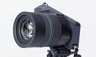
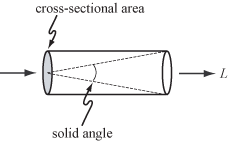
A light field camera, also known as a plenoptic camera, is a camera that captures information about the light field emanating from a scene; that is, the intensity of light in a scene, and also the precise direction that the light rays are traveling in space. This contrasts with conventional cameras, which record only light intensity at various wavelengths.

<span class="mw-page-title-main">Autostereoscopy</span> Any method of displaying stereoscopic images without the use of special headgear or glasses

Autostereoscopy is any method of displaying stereoscopic images without the use of special headgear, glasses, something that affects vision, or anything for eyes on the part of the viewer. Because headgear is not required, it is also called "glasses-free 3D" or "glassesless 3D". There are two broad approaches currently used to accommodate motion parallax and wider viewing angles: eye-tracking, and multiple views so that the display does not need to sense where the viewer's eyes are located. Examples of autostereoscopic displays technology include lenticular lens, parallax barrier, and may include Integral imaging, but notably do not include volumetric display or holographic displays.

<span class="mw-page-title-main">Bidirectional scattering distribution function</span> Mathematical function

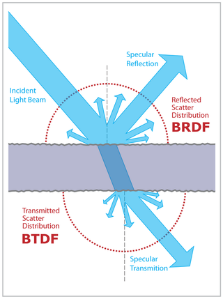
The definition of the BSDF is not well standardized. The term was probably introduced in 1980 by Bartell, Dereniak, and Wolfe. Most often it is used to name the general mathematical function which describes the way in which the light is scattered by a surface. However, in practice, this phenomenon is usually split into the reflected and transmitted components, which are then treated separately as BRDF and BTDF.

<span class="mw-page-title-main">Marc Levoy</span>

Marc Levoy is a computer graphics researcher and Professor Emeritus of Computer Science and Electrical Engineering at Stanford University, a vice president and Fellow at Adobe Inc., and a Distinguished Engineer at Google. He is noted for pioneering work in volume rendering, light fields, and computational photography.

Camera resectioning is the process of estimating the parameters of a pinhole camera model approximating the camera that produced a given photograph or video; it determines which incoming light ray is associated with each pixel on the resulting image. Basically, the process determines the pose of the pinhole camera.

Photon polarization is the quantum mechanical description of the classical polarized sinusoidal plane electromagnetic wave. An individual photon can be described as having right or left circular polarization, or a superposition of the two. Equivalently, a photon can be described as having horizontal or vertical linear polarization, or a superposition of the two.

<span class="mw-page-title-main">3D reconstruction</span> Process of capturing the shape and appearance of real objects

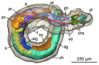
In computer vision and computer graphics, 3D reconstruction is the process of capturing the shape and appearance of real objects. This process can be accomplished either by active or passive methods. If the model is allowed to change its shape in time, this is referred to as non-rigid or spatio-temporal reconstruction.

The derivatives of scalars, vectors, and second-order tensors with respect to second-order tensors are of considerable use in continuum mechanics. These derivatives are used in the theories of nonlinear elasticity and plasticity, particularly in the design of algorithms for numerical simulations.

In continuum mechanics, a compatible deformation tensor field in a body is that unique tensor field that is obtained when the body is subjected to a continuous, single-valued, displacement field. Compatibility is the study of the conditions under which such a displacement field can be guaranteed. Compatibility conditions are particular cases of integrability conditions and were first derived for linear elasticity by Barré de Saint-Venant in 1864 and proved rigorously by Beltrami in 1886.

Lightfieldmicroscopy (LFM) is a scanning-free 3-dimensional (3D) microscopic imaging method based on the theory of light field. This technique allows sub-second (~10 Hz) large volumetric imaging with ~1 μm spatial resolution in the condition of weak scattering and semi-transparence, which has never been achieved by other methods. Just as in traditional light field rendering, there are two steps for LFM imaging: light field capture and processing. In most setups, a microlens array is used to capture the light field. As for processing, it can be based on two kinds of representations of light propagation: the ray optics picture and the wave optics picture. The Stanford University Computer Graphics Laboratory published their first prototype LFM in 2006 and has been working on the cutting edge since then.

References

Theory

Analysis

Cameras

Displays

Archives

Applications