Related Research Articles
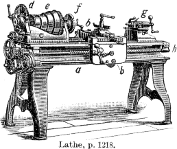
A lathe is a machine tool that rotates a workpiece about an axis of rotation to perform various operations such as cutting, sanding, knurling, drilling, deformation, facing, and turning, with tools that are applied to the workpiece to create an object with symmetry about that axis.

Metalworking is the process of shaping and reshaping metals to create useful objects, parts, assemblies, and large scale structures. As a term it covers a wide and diverse range of processes, skills, and tools for producing objects on every scale: from huge ships, buildings, and bridges down to precise engine parts and delicate jewelry.
A machinist is a tradesperson or trained professional, who not only operates machine tools, but has the knowledge of tooling and materials required to create set ups on machine tools including, but not limited to milling machines, grinders, lathes, and drilling machines.

Machining is a process in which a material is cut into a desired final shape and size by a controlled material-removal process. The processes that have this common theme, controlled material removal, are today collectively known as subtractive manufacturing, in distinction from processes of controlled material addition, which are known as additive manufacturing. Exactly what the "controlled" part of the definition implies can vary, but it almost always implies the use of machine tools.

Drilling is a cutting process that uses a drill bit to cut a hole of circular cross-section in solid materials. The drill bit is usually a rotary cutting tool, often multi-point. The bit is pressed against the work-piece and rotated at rates from hundreds to thousands of revolutions per minute. This forces the cutting edge against the work-piece, cutting off chips (swarf) from the hole as it is drilled.
A reamer is a type of rotary cutting tool used in metalworking. Precision reamers are designed to enlarge the size of a previously formed hole by a small amount but with a high degree of accuracy to leave smooth sides. There are also non-precision reamers which are used for more basic enlargement of holes or for removing burrs. The process of enlarging the hole is called reaming. There are many different types of reamer and they may be designed for use as a hand tool or in a machine tool, such as a milling machine or drill press.

Electrochemical machining (ECM) is a method of removing metal by an electrochemical process. It is normally used for mass production and is used for working extremely hard materials or materials that are difficult to machine using conventional methods. Its use is limited to electrically conductive materials. ECM can cut small or odd-shaped angles, intricate contours or cavities in hard and exotic metals, such as titanium aluminides, Inconel, Waspaloy, and high nickel, cobalt, and rhenium alloys. Both external and internal geometries can be machined.

The phrase speeds and feeds or feeds and speeds refers to two separate velocities in machine tool practice, cutting speed and feed rate. They are often considered as a pair because of their combined effect on the cutting process. Each, however, can also be considered and analyzed in its own right.
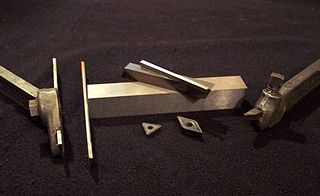
A tool bit is a non-rotary cutting tool used in metal lathes, shapers, and planers. Such cutters are also often referred to by the set-phrase name of single-point cutting tool, as distinguished from other cutting tools such as a saw or water jet cutter. The cutting edge is ground to suit a particular machining operation and may be resharpened or reshaped as needed. The ground tool bit is held rigidly by a tool holder while it is cutting.
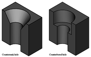
A countersink is a conical hole cut into a manufactured object, or the cutter used to cut such a hole. A common use is to allow the head of a countersunk bolt, screw or rivet, when placed in the hole, to sit flush with or below the surface of the surrounding material. A countersink may also be used to remove the burr left from a drilling or tapping operation thereby improving the finish of the product and removing any hazardous sharp edges.
A grinding dresser or wheel dresser is a tool to dress the surface of a grinding wheel. Grinding dressers are used to return a wheel to its original round shape, to expose fresh grains for renewed cutting action, or to make a different profile on the wheel's edge.

Turning is a machining process in which a cutting tool, typically a non-rotary tool bit, describes a helix toolpath by moving more or less linearly while the workpiece rotates.
Milling cutters are cutting tools typically used in milling machines or machining centres to perform milling operations. They remove material by their movement within the machine or directly from the cutter's shape.

A metal lathe or metalworking lathe is a large class of lathes designed for precisely machining relatively hard materials. They were originally designed to machine metals; however, with the advent of plastics and other materials, and with their inherent versatility, they are used in a wide range of applications, and a broad range of materials. In machining jargon, where the larger context is already understood, they are usually simply called lathes, or else referred to by more-specific subtype names. These rigid machine tools remove material from a rotating workpiece via the movements of various cutting tools, such as tool bits and drill bits.

In machining, boring is the process of enlarging a hole that has already been drilled by means of a single-point cutting tool, such as in boring a gun barrel or an engine cylinder. Boring is used to achieve greater accuracy of the diameter of a hole, and can be used to cut a tapered hole. Boring can be viewed as the internal-diameter counterpart to turning, which cuts external diameters.

Grinding is an abrasive machining process that uses a grinding wheel as the cutting tool.
Vibration is a mechanical phenomenon whereby oscillations occur about an equilibrium point. The word comes from Latin vibrationem. The oscillations may be periodic, such as the motion of a pendulum—or random, such as the movement of a tire on a gravel road.
Vibratory Stress Relief, often abbreviated VSR, is a non-thermal stress relief method used by the metal working industry to enhance the dimensional stability and mechanical integrity of castings, forgings, and welded components, chiefly for two categories of these metal workpieces:

Milling is the process of machining using rotary cutters to remove material by advancing a cutter into a workpiece. This may be done varying direction on one or several axes, cutter head speed, and pressure. Milling covers a wide variety of different operations and machines, on scales from small individual parts to large, heavy-duty gang milling operations. It is one of the most commonly used processes for machining custom parts to precise tolerances.
Virtual machining is the practice of using computers to simulate and model the use of machine tools for part manufacturing. Such activity replicates the behavior and errors of a real environment in virtual reality systems. This can provide useful ways to manufacture products without physical testing on the shop floor. As a result, time and cost of part production can be decreased.
References
- ↑ "Abrasives Training Dressing and Truing - Tooling U-SME". www.toolingu.com.
- ↑ S. A. Tobias and W. Fishwick, “A theory of Regenerative chatter,” The Engineer-London, 1958.
- ↑ Daghini, L. (2012). Improving Machining System Performance through designed-in Damping: Modelling, Analysis and Design Solutions. (Doctoral dissertation). Stockholm: KTH Royal Institute of Technology
- ↑ Archenti, A., 2011. A Computational Framework for Control of Machining System Capability: from formulation to implementation (Doctoral dissertation, KTH Royal Institute of Technology).
- ↑ Rashid, A., 2005. On passive and active control of machining system dynamics: analysis and implementation (Doctoral dissertation, KTH).
- ↑ Österlind, T., 2017. Estimation of Machining System Dynamic Properties-Measurement and Modelling (Doctoral dissertation, Kungliga Tekniska högskolan).
- ↑ Altintas, Yusuf. Manufacturing Automation: Metal Cutting Mechanics, Machine Tool Vibrations, and CNC Design. Cambridge University Press, 2000, ISBN 978-0-521-65973-4
- ↑ Cheng, Kai. Machining Dynamics: Fundamentals, Applications and Practices. Springer, 2008, ISBN 978-1-84628-367-3
- ↑ Schmitz, Tony L., Smith, Scott K. Machining Dynamics: Frequency Response to Improved Productivity. Springer, 2008, ISBN 978-0-387-09644-5
- ↑ Maekawa, Obikawa. Metal Machining: Theory and Applications. Butterworth-Heinemann, 2000, ISBN 978-0-340-69159-5