Turning

Last updated
Roughing, or rough turning SchruppenDrehen.jpg
Roughing, or rough turning
Parting aluminium StechenDrehen.jpg
Parting aluminium
Finish turning SchlichtenDrehen.jpg
Finish turning

Turning is a machining process in which a cutting tool, typically a non-rotary tool bit, describes a helix toolpath by moving more or less linearly while the workpiece rotates.

Contents

Usually the term "turning" is reserved for the generation of external surfaces by this cutting action, whereas this same essential cutting action when applied to internal surfaces (holes, of one kind or another) is called "boring". Thus the phrase "turning and boring" categorizes the larger family of processes known as lathing. The cutting of faces on the workpiece, whether with a turning or boring tool, is called "facing", and may be lumped into either category as a subset.

Turning can be done manually, in a traditional form of lathe, which frequently requires continuous supervision by the operator, or by using an automated lathe which does not. Today the most common type of such automation is computer numerical control, better known as CNC. (CNC is also commonly used with many other types of machining besides turning.)

When turning, the workpiece (a piece of relatively rigid material such as wood, metal, plastic, or stone) is rotated and a cutting tool is traversed along 1, 2, or 3 axes of motion to produce precise diameters and depths. Turning can be either on the outside of the cylinder or on the inside (also known as boring) to produce tubular components to various geometries. Although now quite rare, early lathes could even be used to produce complex geometric figures, even the platonic solids; although since the advent of CNC it has become unusual to use non-computerized toolpath control for this purpose.

The turning processes are typically carried out on a lathe, considered to be the oldest of machine tools, and can be of different types such as straight turning, taper turning, profiling or external grooving. Those types of turning processes can produce various shapes of materials such as straight, conical, curved, or grooved workpieces. In general, turning uses simple single-point cutting tools. Each group of workpiece materials has an optimum set of tool angles that have been developed through the years.

The bits of waste metal from turning operations are known as chips (North America), or swarf (Britain). In some areas they may be known as turnings.

The tool's axes of movement may be literally a straight line, or they may be along some set of curves or angles, but they are essentially linear (in the non mathematical sense).

A component that is subject to turning operations can be termed as a “Turned Part” or “Machined Component”. Turning operations are carried out on a lathe machine which can be manually or CNC operated.

Turning operations

Turning specific operations include:

Turning
Turning Langs-Rund-Drehen.jpg
Turning

The general process of turning involves rotating a part while a single-point cutting tool is moved parallel to the axis of rotation. [1] Turning can be done on the external surface of the part as well as the internal surface (the process known as boring). The starting material is generally a workpiece generated by other processes such as casting, forging, extrusion, or drawing.

Tapered turning
Tapered turning produces a cylindrical shape that gradually decreases in diameter from one end to the other. This can be achieved a) from the compound slide b) from taper turning attachment c) using a hydraulic copy attachment d) using a C.N.C. lathe e) using a form tool f) by the offsetting of the tailstock - this method more suited for shallow tapers. [2]
Spherical generation
Spherical generation produces a spherical finished surface by turning a form around a fixed axis of revolution. Methods include a) using hydraulic copy attachment b) C.N.C. (computerised numerically controlled) lathe c) using a form tool (a rough and ready method) d) using bed jig (need drawing to explain). [2]
Hard turning
Hard turning is a type of turning done on materials with a Rockwell C hardness greater than 45. It is typically performed after the workpiece is heat treated. [3]
The process is intended to replace or limit traditional grinding operations. Hard turning, when applied for purely stock removal purposes, competes favorably with rough grinding. However, when it is applied for finishing where form and dimension are critical, grinding is superior. Grinding produces higher dimensional accuracy of roundness and cylindricity. In addition, polished surface finishes of Rz=0.3-0.8z cannot be achieved with hard turning alone. Hard turning is appropriate for parts requiring a roundness accuracy of 0.5-12 micrometres, and/or surface roughness of Rz 0.8–7.0 micrometres. It is used for gears, injection pump components, and hydraulic components, among other applications. [3]
Facing
Facing Quer-Plan-Drehen.jpg
Facing

Facing in the context of turning work involves moving the cutting tool at right angles to the axis of rotation of the rotating workpiece. [1] This can be performed by the operation of the cross-slide, if one is fitted, as distinct from the longitudinal feed (turning). It is frequently the first operation performed in the production of the workpiece, and often the last—hence the phrase "ending up".

Parting

This process, also called parting off or cutoff, is used to create deep grooves which will remove a completed or part-complete component from its parent stock.

Grooving
External grooving Quer-Rund-Drehen.jpg
External grooving
Face grooving Langs-Plan-Drehen.jpg
Face grooving

Grooving is like parting, except that grooves are cut to a specific depth instead of severing a completed/part-complete component from the stock. Grooving can be performed on internal and external surfaces, as well as on the face of the part (face grooving or trepanning).

Non-specific operations include:

Boring
Enlarging or smoothing an existing hole created by drilling, moulding etc.i.e. the machining of internal cylindrical forms (generating) a) by mounting workpiece to the spindle via a chuck or faceplate b) by mounting workpiece onto the cross slide and placing cutting tool into the chuck. This work is suitable for castings that are too awkward to mount in the face plate. On long bed lathes large workpiece can be bolted to a fixture on the bed and a shaft passed between two lugs on the workpiece and these lugs can be bored out to size. A limited application but one that is available to the skilled turner/machinist. [2]
Drilling
is used to remove material from the inside of a workpiece. This process utilizes standard drill bits held stationary in the tail stock or tool turret of the lathe. The process can be done by separately available drilling machines.
Knurling Randelwerkzeug.jpg
Knurling
Knurling
The cutting of a serrated pattern onto the surface of a part to use as a hand grip or as a visual enhancement using a special purpose knurling tool. [2]
Reaming
The sizing operation that removes a small amount of metal from a hole already drilled. [2] It is done for making internal holes of very accurate diameters. For example, a 6mm hole is made by drilling with 5.98 mm drill bit and then reamed to accurate dimensions.
Threading
Both standard and non-standard screw threads can be turned on a lathe using an appropriate cutting tool. (Usually having a 60, or 55° nose angle) Either externally, or within a bore (tapping operation is a process of making threads either inner or outer in an work piece. [4] Generally referred to as single-point threading.
tapping of threaded nuts and holes a) using hand taps and tailstock centre b)using a tapping device with a slipping clutch to reduce risk of breakage of the tap. [2]
threading operations include a)all types of external and internal thread forms using a single point tool also taper threads, double start threads, multi start threads, worms as used in worm wheel reduction boxes, leadscrew with single or multistart threads. b) by the use of threading boxes fitted with 4 form tools, up to 2" diameter threads but it is possible to find larger boxes than this. [2]
Polygonal turning
in which non-circular forms are machined without interrupting the rotation of the raw material.

Lathes

A lathe is a machine tool used principally for shaping pieces of metal, wood, or other materials by causing the workpiece to be held and rotated by the lathe while a tool bit is advanced into the work causing the cutting action. Lathes can be divided into three types for easy identification: engine lathe, turret lathe, and special purpose lathes. Some smaller ones are bench mounted and semi-portable. The larger lathes are floor mounted and may require special transportation if they must be moved. Field and maintenance shops generally use a lathe that can be adapted to many operations and that is not too large to be moved from one work site to another. The engine lathe is ideally suited for this purpose. A trained operator can accomplish more machining jobs with the engine lathe than with any other machine tool. Turret lathes and special purpose lathes are usually used in production or job shops for mass production or specialized parts, while basic engine lathes are usually used for any type of lathe work.


Over the years, in the manufacturing industry, with the improvement of the difficulty of product processing, the emergence of CNC turning milling compound centers, which maintains the characteristics of lathe machining, but also increased the function of the milling machine, the combination of the two to improve production efficiency.

Workholding methods

Collets HardingeR8Collets.jpg
Collets

Tooling

The various angles, shapes, and sizes of a single-point cutting tool have direct relation to the resulting surface of a workpiece in machining operations. Different types of angle such as rake angle , side rake angle, cutting-edge angle, relief angle, nose radius exist and may be different with respect to the workpiece. Also, there are many shapes of single-point cutting tools, such as V-shaped and Square. Usually, a special toolholder is used to hold the cutting tool firmly during operation.

Dynamics of turning

Forces

The relative forces in a turning operation are important in the design of machine tools. The machine tool and its components must be able to withstand these forces without causing significant deflections, vibrations, or chatter during the operation. There are three principal forces during a turning process:

Speeds and feeds

Speeds and feeds for turning are chosen based on cutter material, workpiece material, setup rigidity, machine tool rigidity and spindle power, coolant choice, and other factors.

Feed

See also

Related Research Articles

<span class="mw-page-title-main">Lathe</span> Machine tool which rotates the work piece on its axis

A lathe is a machine tool that rotates a workpiece about an axis of rotation to perform various operations such as cutting, sanding, knurling, drilling, deformation, facing, and turning, with tools that are applied to the workpiece to create an object with symmetry about that axis.

<span class="mw-page-title-main">Metalworking</span> Process of making items from metal

Metalworking is the process of shaping and reshaping metals to create useful objects, parts, assemblies, and large scale structures. As a term it covers a wide and diverse range of processes, skills, and tools for producing objects on every scale: from huge ships, buildings, and bridges down to precise engine parts and delicate jewelry.

<span class="mw-page-title-main">Machinist</span> Technician

A machinist is a tradesperson or trained professional who operates machine tools, and has the ability to set up tools such as milling machines, grinders, lathes, and drilling machines.

<span class="mw-page-title-main">Machining</span> Material-removal process; manufacturing process

Machining is a manufacturing process whereby a desired shape or part is achieved by the controlled removal of material from a larger piece of raw material by cutting; it is most often performed with metal material. These processes are collectively called subtractive manufacturing, which utilizes machine tools, in contrast to additive manufacturing, which uses controlled addition of material.

<span class="mw-page-title-main">Drill bit</span> Type of cutting tool

Drill bits are cutting tools used in a drill to remove material to create holes, almost always of circular cross-section. Drill bits come in many sizes and shapes and can create different kinds of holes in many different materials. In order to create holes drill bits are usually attached to a drill, which powers them to cut through the workpiece, typically by rotation. The drill will grasp the upper end of a bit called the shank in the chuck.

<span class="mw-page-title-main">Drilling</span> Cutting process that uses a drill bit to cut a circular hole into the workpiece

Drilling is a cutting process where a drill bit is spun to cut a hole of circular cross-section in solid materials. The drill bit is usually a rotary cutting tool, often multi-point. The bit is pressed against the work-piece and rotated at rates from hundreds to thousands of revolutions per minute. This forces the cutting edge against the work-piece, cutting off chips (swarf) from the hole as it is drilled.

A reamer is a type of rotary cutting tool used in metalworking. Precision reamers are designed to enlarge the size of a previously formed hole by a small amount but with a high degree of accuracy to leave smooth sides. There are also non-precision reamers which are used for more basic enlargement of holes or for removing burrs. The process of enlarging the hole is called reaming. There are many different types of reamer and they may be designed for use as a hand tool or in a machine tool, such as a milling machine or drill press.

<span class="mw-page-title-main">Speeds and feeds</span> Two separate velocities in machine tool practice, cutting speed and feed rate

The phrase speeds and feeds or feeds and speeds refers to two separate velocities in machine tool practice, cutting speed and feed rate. They are often considered as a pair because of their combined effect on the cutting process. Each, however, can also be considered and analyzed in its own right.

<span class="mw-page-title-main">Collet</span> Type of chuck

A collet is a segmented sleeve, band or collar. One of the two radial surfaces of a collet is usually tapered and the other is cylindrical. The term collet commonly refers to a type of chuck that uses collets to hold either a workpiece or a tool but has other mechanical applications.

<span class="mw-page-title-main">Countersink</span> Conical hole cut so a fastener can be inserted flush with the surface

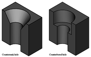
In manufacturing, a countersink is a conical hole cut into a manufactured object, or the cutter used to cut such a hole. A common use is to allow the head of a countersunk bolt, screw or rivet, when placed in the hole, to sit flush with or below the surface of the surrounding material. A countersink may also be used to remove the burr left from a drilling or tapping operation, thereby improving the finish of the product and removing any hazardous sharp edges.

<span class="mw-page-title-main">Chuck (engineering)</span> Clamp used to hold an object with radial symmetry, especially a cylinder

A chuck is a specialized type of clamp used to hold an object with radial symmetry, especially a cylinder. In a drill, a mill and a transmission, a chuck holds the rotating tool; in a lathe, it holds the rotating workpiece.

<span class="mw-page-title-main">Lathe center</span>

A lathe center, often shortened to center, is a tool that has been ground to a point to accurately position a workpiece on an axis. They usually have an included angle of 60°, but in heavy machining situations an angle of 75° is used.

<span class="mw-page-title-main">Metal lathe</span> Machine tool used to remove material from a rotating workpiece

In machining, a metal lathe or metalworking lathe is a large class of lathes designed for precisely machining relatively hard materials. They were originally designed to machine metals; however, with the advent of plastics and other materials, and with their inherent versatility, they are used in a wide range of applications, and a broad range of materials. In machining jargon, where the larger context is already understood, they are usually simply called lathes, or else referred to by more-specific subtype names. These rigid machine tools remove material from a rotating workpiece via the movements of various cutting tools, such as tool bits and drill bits.

<span class="mw-page-title-main">Indexing head</span> Dividing head

An indexing head, also known as a dividing head or spiral head, is a specialized tool that allows a workpiece to be circularly indexed; that is, easily and precisely rotated to preset angles or circular divisions. Indexing heads are usually used on the tables of milling machines, but may be used on many other machine tools including drill presses, grinders, and boring machines. Common jobs for a dividing head include machining the flutes of a milling cutter, cutting the teeth of a gear, milling curved slots, or drilling a bolt hole circle around the circumference of a part.

<span class="mw-page-title-main">Boring (manufacturing)</span> Process of enlarging an already-drilled hole with a single-point cutting tool

In machining, boring is the process of enlarging a hole that has already been drilled by means of a single-point cutting tool, such as in boring a gun barrel or an engine cylinder. Boring is used to achieve greater accuracy of the diameter of a hole, and can be used to cut a tapered hole. Boring can be viewed as the internal-diameter counterpart to turning, which cuts external diameters.

In the context of machining, a cutting tool or cutter is typically a hardened metal tool that is used to cut, shape, and remove material from a workpiece by means of machining tools as well as abrasive tools by way of shear deformation. The majority of these tools are designed exclusively for metals.

<span class="mw-page-title-main">Grinding (abrasive cutting)</span> Machining process using a grinding wheel

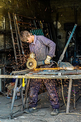
Grinding is a type of abrasive machining process which uses a grinding wheel as cutting tool.

<span class="mw-page-title-main">Burnishing (metal)</span> Deformation of a metal surface due to friction

Burnishing is the plastic deformation of a surface due to sliding contact with another object. It smooths the surface and makes it shinier. Burnishing may occur on any sliding surface if the contact stress locally exceeds the yield strength of the material. The phenomenon can occur both unintentionally as a failure mode, and intentionally as part of a metalworking or manufacturing process. It is a squeezing operation under cold working.

In manufacturing, threading is the process of creating a screw thread. More screw threads are produced each year than any other machine element. There are many methods of generating threads, including subtractive methods ; deformative or transformative methods ; additive methods ; or combinations thereof.

<span class="mw-page-title-main">Milling (machining)</span> Removal of material from a workpiece using rotating tools

Milling is the process of machining using rotary cutters to remove material by advancing a cutter into a workpiece. This may be done by varying directions on one or several axes, cutter head speed, and pressure. Milling covers a wide variety of different operations and machines, on scales from small individual parts to large, heavy-duty gang milling operations. It is one of the most commonly used processes for machining custom parts to precise tolerances.

References

  1. 1 2 Todd, Robert H.; Allen, Dell K.; Al ting, Leo (1994), Manufacturing Processes Reference Guide, Industrial Press Inc., p. 153, ISBN   0-8311-3049-0.
  2. 1 2 3 4 5 6 7 Workshop Technology by W.A.J. Chapman Ph.D. M.Sc.(Eng.), M.I.Mech.E., M.I.Prod.E. Principal Hatfield College of Technology, Hertfordshire first published 1951 part one, two and three published by Edward Arnold (publishers Limited
  3. 1 2 Koepfer, Chris (2010-01-22). "Hard Turning as an Alternative to Grinding". Production Machining. Retrieved 2010-03-04.
  4. "Threading On A Lathe : Modern Machine Shop". Mmsonline.com. 2003-01-15. Retrieved 2012-03-13.